Cutting system for shaping stage light beams and stage lamp

A technology of beam shaping and stage lighting, which is applied in the direction of light source fixing, lighting device parts, lighting devices, etc., can solve the problems of limited operating freedom of cutting components, slow cutting speed, inaccurate positioning, etc., and achieve convenient transportation and storage Placement, precise positioning of the cutting piece, and the effect of preventing motion movement

Active Publication Date: 2015-01-28
GUANGZHOU FINEART LIGHTING
View PDF7 Cites 3 Cited by
  • Summary
  • Abstract
  • Description
  • Claims
  • Application Information

AI Technical Summary

Problems solved by technology

[0004] In the prior art, the transmission structure of the cutting assembly generally adopts a transmission structure such as a screw or a screw. Although this structure can realize the purpose of driving the cutting assembly, it has the following defects: (1) The cutting speed is too slow, and it is difficult to Make the cutting components obtain a faster cutting speed, thereby affecting the beam cutting effect of the stage lamps and stage performances; (2) It takes up a lot of space, so that the entire lamp is relatively large and cumbersome; (3) The movement is not flexible , the operating freedom of the cutting components is limited, so that some beam shape effects cannot be obtained by cutting; (4) Due to the gap between the cutting disc and the transmission mechanism, the cutting disc is easy to move, and the positioning is not accurate, which seriously affects the expected cutting Effect
Other types of transmission structures are often complex in structure and occupy a large maneuvering space, which cannot meet the needs of reducing the size of the lamp and realizing fast cutting and flexible movement at the same time.

Method used


Image

  • Cutting system for shaping stage light beams and stage lamp
  • Cutting system for shaping stage light beams and stage lamp
  • Cutting system for shaping stage light beams and stage lamp

Examples


Embodiment Construction

[0036] The structure and working principle of the present invention will be described in detail below in conjunction with the accompanying drawings.

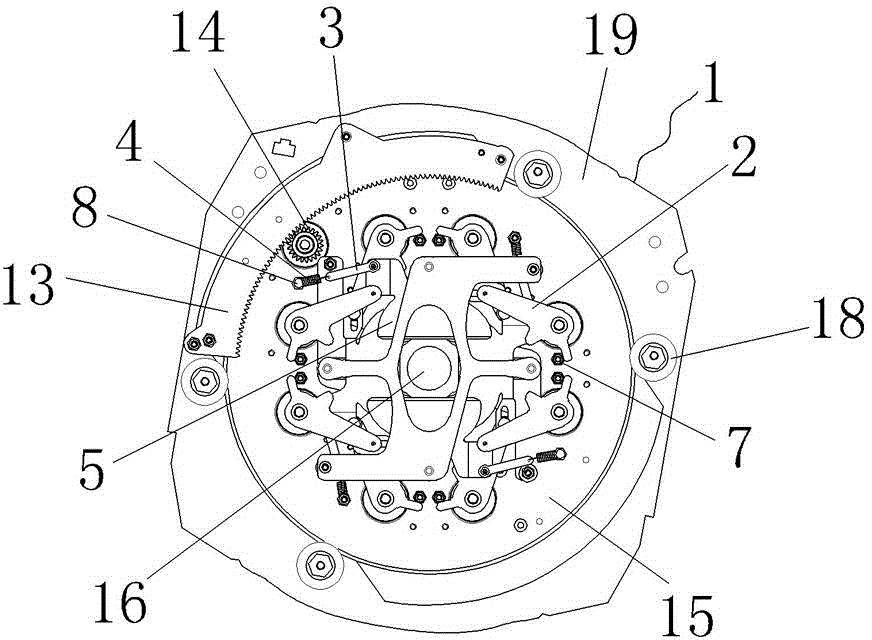
[0037] refer to Figure 1-Figure 6 , the cutting system used for stage lighting beam shaping includes:

[0038] Bracket 1, the bracket 1 includes a fixed frame 19 and a rotating disk 15, the fixed frame 19 is fixed on the support frame inside the lamp, the rotating disk 15 is connected to the fixed frame 19 through a rotating drive mechanism and can rotate relative to the fixed frame 19;

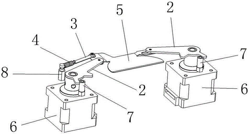
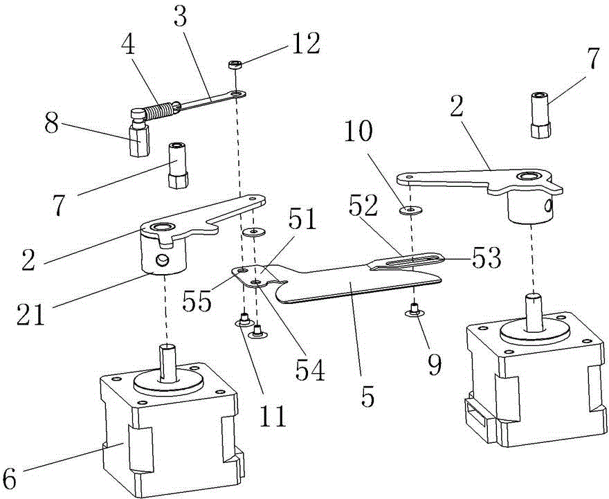
[0039] A cutting device consisting of four groups of cutting blades 5, each group of cutting blades 5 is arranged in a different plane perpendicular to the light beam, and each group of cutting blades 5 can move along the plane where it is located;

[0040] Four pairs of actuators, each pair of actuators are connected to a group of cutting blades 5; each actuator includes a drive motor 6 and a transmission mechanism, and the drive motor 6 is ...


PUM


Abstract

The invention discloses a cutting system for shaping stage light beams, which comprises a support, a cutting device and four pairs of executing mechanisms, wherein the cutting device comprises four sets of cutting blades; the cutting blades are arranged in different planes orthogonal to a light beam and can move along the corresponding plane; each pair of executing mechanisms is connected with one set of cutting blades and comprises a driving motor and a transmission mechanism, and the driving motor is arranged on the support; the transmission mechanism further comprises a rotary rod; and one end of the rotary rod is fixedly connected with an output shaft of the driving motor, and the other end of the rotary rod is movably connected with the corresponding cutting blade. Because the rotary rod and the output shaft of the motor can synchronously rotate, the rotation of the driving motor can be rapidly transmitted to the cutting blades so as to get a high cutting speed and even the stroboscopic effect of cutting.

Description

technical field [0001] The invention relates to the field of stage lighting fixture equipment, in particular to a cutting system for beam shaping of stage lighting and a stage lamp using the cutting system. Background technique [0002] In the field of stage technology, a beam shaping component is usually arranged between the light source of the stage lamp and the light-emitting objective lens to intercept the beam so as to obtain a beam with a specific shape. [0003] The cutting component is one of the typical beam shaping components, which can be used to obtain a beam of arbitrary shape profile, and can also adjust the size of the beam. In stage performances, the lighting engineer will cut the light spots projected by the lamps into various shapes according to the needs of the plot or scene. [0004] In the prior art, the transmission structure of the cutting assembly generally adopts a transmission structure such as a screw or a screw. Although this structure can realiz...

Claims


Application Information

Patent Timeline
Patent Type & Authority Patents(China)
IPC IPC(8): F21V14/00
Inventor 刘建华
Owner GUANGZHOU FINEART LIGHTING
Why Eureka
Try Eureka