Display panel and color optical filter

A color filter, display panel technology, applied in optics, optical elements, nonlinear optics, etc., can solve the problem of reducing the image brightness of display devices, and achieve the effect of improving color saturation and brightness, and expanding display color gamut

Active Publication Date: 2012-11-28
AU OPTRONICS CORP
View PDF4 Cites 1 Cited by
  • Summary
  • Abstract
  • Description
  • Claims
  • Application Information

AI Technical Summary

Problems solved by technology

Although the color filter can filter the passing light into a variety of monochromatic lights, so that the display device can achieve a color display effect by mix

Method used


Image

  • Display panel and color optical filter
  • Display panel and color optical filter
  • Display panel and color optical filter

Examples


Embodiment Construction

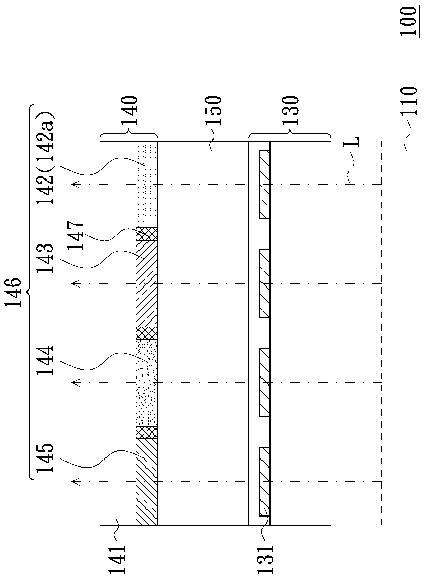
[0027] figure 1 It is a schematic cross-sectional view of a display panel according to an embodiment of the present invention. Please refer to figure 1 , the display panel 100 includes an active element array substrate 130 , a color filter 140 and a display medium layer 150 . The display medium layer 150 is disposed between the active element array substrate 130 and the color filter 140 . The active element array substrate 130 includes a plurality of driving elements 131 ( figure 1 Only four are shown), which includes, for example, a thin film transistor (TFT), a pixel electrode, a scan line and a data line (not shown). The display medium layer 150 is, for example, a liquid crystal layer, but the present invention is not limited thereto. In other embodiments, the display medium layer can also be an electro-phoretic layer, an electro-wetting layer, or other medium layers whose light transmittance can be controlled by changing the magnitude of the electric field.

[0028] A...


PUM


Abstract

The invention discloses a display panel and a color optical filter. The display panel comprises an active element array substrate, a display medium layer and a color optical filter. The color optical filter is arranged above the active element array substrate, and comprises a substrate and a yellow optical resistor arranged on the substrate, wherein the yellow optical resistor comprises a first fluorescent material, and the penetration rate of the yellow optical resistor between 600 nm light penetration spectrum and 800 nm light penetration spectrum is greater than 1, and the display medium layer is arranged between the active element array substrate and the color optical filter. The display panel and the color optical filter of the invention enable the picture color saturation and brightness displayed by the display panel to be improved.

Description

technical field [0001] The present invention relates to a display panel, and more particularly, to a display panel with a color filter. Background technique [0002] Liquid crystal display devices have become an important application of today's display technology due to their advantages of high image quality, good contrast, wide viewing angle, and color saturation. A common color liquid crystal display device includes a color filter, a driving element array substrate, and a liquid crystal layer disposed therebetween. Although the color filter can filter the passing light into a variety of monochromatic lights, so that the display device can achieve the effect of color display by the mixed or independent output of these monochromatic lights, but the color filter will also Decreases the brightness of the image displayed by the display device. It can be seen from this that improving the color saturation and light transmittance of the color filter is the focus of development i...

Claims


Application Information

Patent Timeline
IPC IPC(8): G02B5/22G02F1/1335
CPCG02B5/201G02B5/22G02B2207/113
Inventor 王英力陈奎百廖烝贤
Owner AU OPTRONICS CORP
Why Eureka
Try Eureka