Sealing body for electrolytic capacitor and electrolytic capacitor

A technology for electrolytic capacitors and sealing bodies, which is applied to liquid electrolytic capacitors, capacitor casings/packages, capacitor parts, etc., can solve the problems of large waste of materials and troublesome lamination processes, and achieve the effect of excellent heat resistance.

Inactive Publication Date: 2012-11-28
TOTSUPU PAATSU
View PDF6 Cites 3 Cited by
  • Summary
  • Abstract
  • Description
  • Claims
  • Application Information

AI Technical Summary

Problems solved by technology

However, such a laminated sheet is not only troublesome in the lamination process of the material, punching, etc., but also the rubber sheet is laminated to a part that does not need airtightness, so the waste of material is large.

Method used


Image

  • Sealing body for electrolytic capacitor and electrolytic capacitor
  • Sealing body for electrolytic capacitor and electrolytic capacitor
  • Sealing body for electrolytic capacitor and electrolytic capacitor

Examples


no. 1 Embodiment approach

[0027] use Figure 1 ~ Figure 3 The first embodiment will be described.

[0028] (constitute)

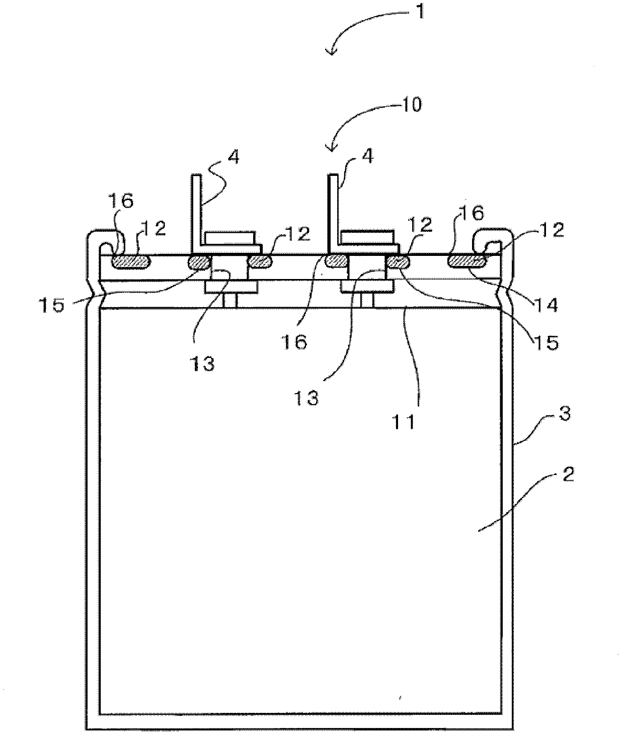
[0029] Such as figure 1 As shown, the electrolytic capacitor 1 of the present embodiment includes a capacitor element 2 , a case 3 , electrodes 4 provided with connection terminals for connection to external devices, and a disc-shaped sealing body 10 . The sealing body 10 has a sealing plate 11 and an elastic body 12 . The sealing plate 11 is produced by injection molding a thermoplastic resin as an example. The elastic body 12 is formed by integrally molding a thermoplastic resin on the sealing plate 11 by bimaterial molding. Bi-material forming is integrally produced by combining different materials using the same mold.

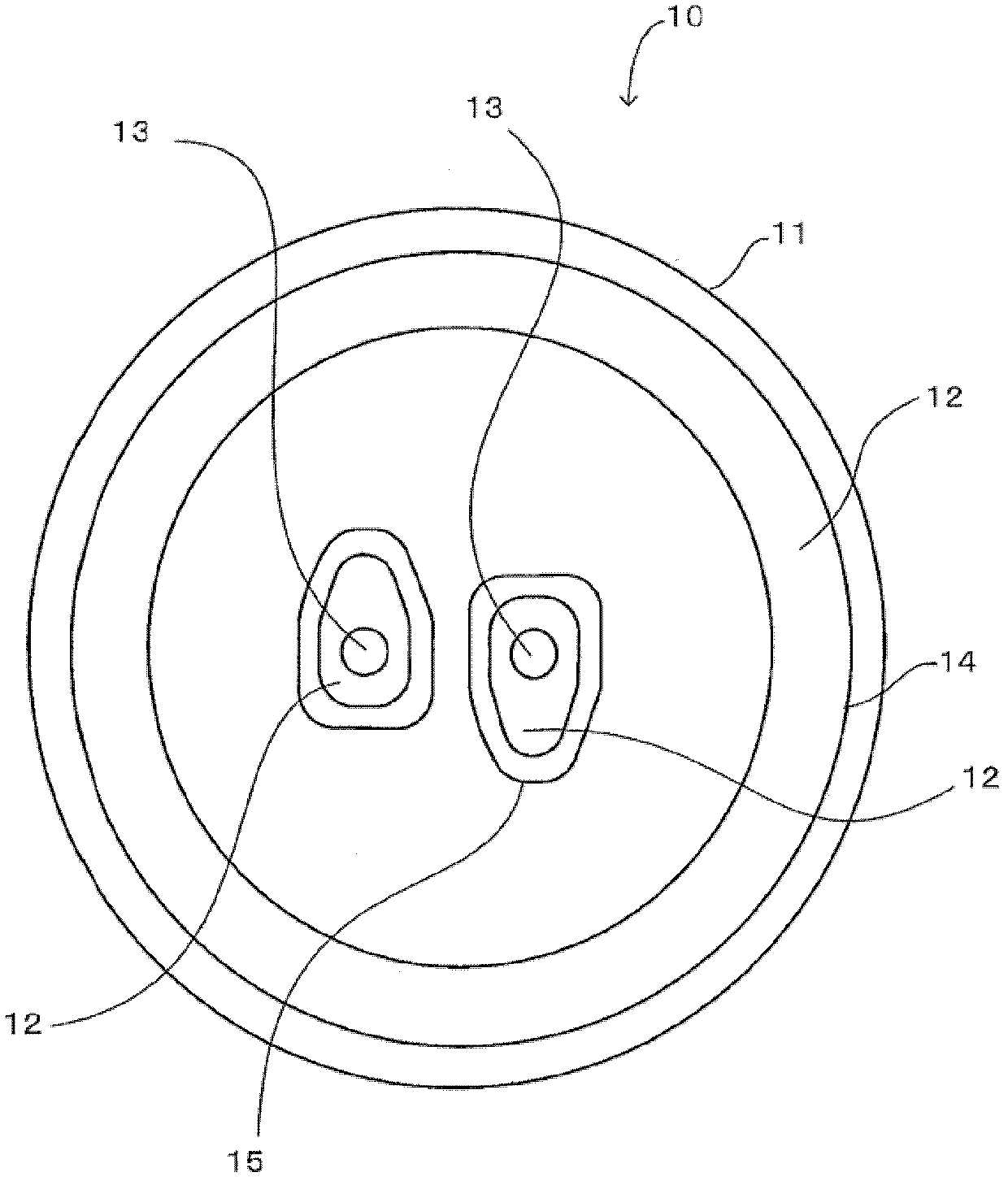
[0030] That is, the above-mentioned sealing plate 11 is as figure 2 It has a disc shape as shown. Syndiotactic polystyrene resin (SPS) is mentioned as a thermoplastic resin used as the sealing plate 11. As shown in FIG. The syndiotactic polystyrene resi...

no. 2 Embodiment approach

[0047] Use below Figure 4 The second embodiment will be described. and, figure 1 , figure 2 The configuration shown is the same as that of the first embodiment, and description thereof will be omitted.

[0048] (constitute)

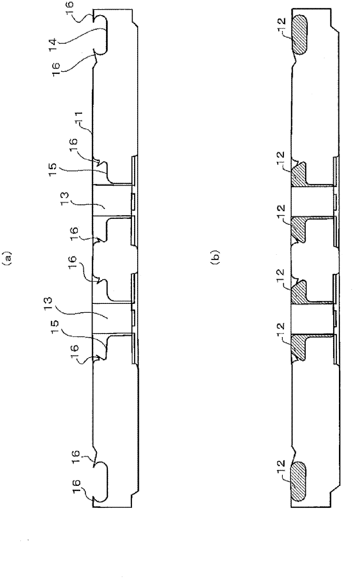
[0049] The sealing plate 11 of the present embodiment is as Figure 4 As shown in (a), protruding portions 17 that become protrusions 16 after deformation are provided at the edge portions of the respective grooves. The protruding portion 17 is formed along a direction parallel to the inner surface of the groove portion at an edge portion of the annular groove portion 14 and the electrode groove portion 15 . That is, the protruding portion 17 stands substantially upward from the openings of the groove portions 14 and 15 so as to stand up from the sealing plate 11 . Therefore, in the state where the sealing plate 11 is molded, the opening of each groove 14, 15 is equal to the width of each groove 14, 15, unlike the case where the opening is narrow...


PUM


Abstract

The invention provides a sealing body for an electrolytic capacitor and an electrolytic capacitor. The sealing body is excellent in gas tightness and production rate. The electrolytic capacitor is composed of a capacitor element (2), a housing (3), an electrode (4) of a connecting terminal which is connected with an external device, and the sealing body (10). The sealing body (10) is provided with a thermoplastic sealing plate (11) and elastic bodies (12). The sealing plate (11) is provided with electrode holes (13) in which the electrodes are inserted, circular grooves (14), and electrode grooves (15) which are arranged on the periphery of the electrode holes (13). The elastic bodies (12) are filled in the circular grooves (14) of the sealing plate (11) and the electrode grooves (15). The elastic bodies which are solidified are locked by protruding parts (16) arranged on internal faces of the electrode grooves (15) and the circular grooves (14). The sealing body (10) is arranged on an opening part of the housing (3). The front end of the housing (3) is curled. The front end of the housing (3) presses the elastic bodies (12), and the housing (3) is sealed.

Description

technical field [0001] The present invention relates to a sealing body that seals an opening of a casing of an electrolytic capacitor, and an electrolytic capacitor using the sealing body. Background technique [0002] An electrolytic capacitor is constructed by accommodating a capacitor element impregnated with an electrolytic solution in a cylindrical case made of aluminum or the like and sealing the opening of the case with a sealing body provided with electrodes. , thus forming an electrolytic capacitor. The sealing body requires airtightness, chemical resistance, and electrical insulation. For this reason, an elastic body such as rubber with excellent airtightness, chemical resistance, and electrical insulation is used for the sealing part between the sealing body and the housing. Airtight components. [0003] As such a sealing body, conventionally, a sealing body obtained by punching out a laminated plate in which an airtight rubber sheet is bonded to the entire uppe...

Claims


Application Information

Patent Timeline
IPC IPC(8): H01G9/08H01G9/145
Inventor 岛贯健藏
Owner TOTSUPU PAATSU
Why Eureka
Try Eureka