Driving method for plasma display panel, and plasma display device

A technology for display panels and driving methods, applied to static indicators, color TV parts, TV system parts, etc., can solve problems such as wrong write discharge, image display quality deterioration, etc., to achieve suppression of abnormal discharge, The effect of improving image display quality

Inactive Publication Date: 2012-11-28
PANASONIC CORP
View PDF9 Cites 0 Cited by
  • Summary
  • Abstract
  • Description
  • Claims
  • Application Information

AI Technical Summary

Problems solved by technology

Furthermore, if unnecessary wall charges are excessively accumulated in the discharge cells, for example, erroneous address discharges may occur in discharge cells where address discharges should not occur, and image display quality may deteriorate.

Method used


Image

  • Driving method for plasma display panel, and plasma display device
  • Driving method for plasma display panel, and plasma display device
  • Driving method for plasma display panel, and plasma display device

Examples


Embodiment approach 1

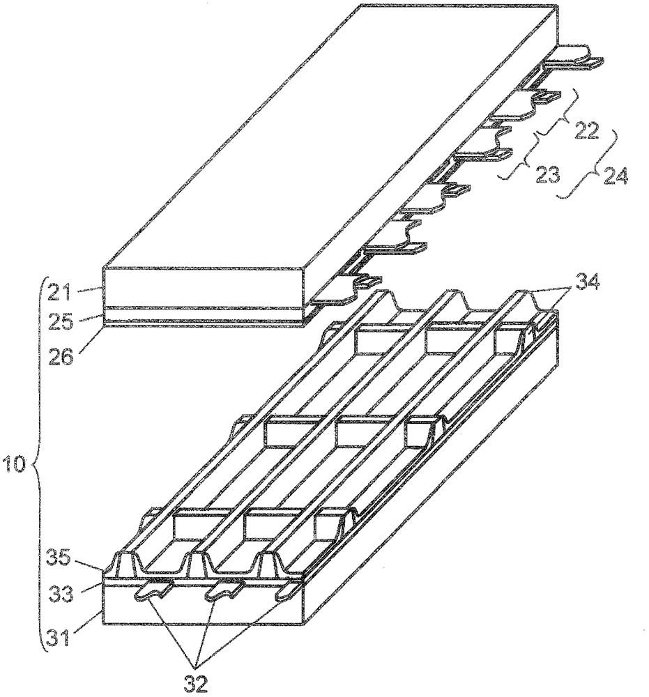
[0039] figure 1 It is an exploded perspective view showing the structure of the panel 10 in Embodiment 1 of this invention. On front panel 21 made of glass, a plurality of display electrode pairs 24 including scan electrodes 22 and sustain electrodes 23 are formed. Furthermore, dielectric layer 25 is formed to cover scan electrodes 22 and sustain electrodes 23 , and protective layer 26 is formed on dielectric layer 25 . The protective layer 26 is formed of a material mainly composed of magnesium oxide (MgO).

[0040] A plurality of data electrodes 32 are formed on rear plate 31 , dielectric layer 33 is formed to cover data electrodes 32 , and grid-shaped partition walls 34 are further formed thereon. Further, phosphor layers 35 that emit light of each color of red (R), green (G) and blue (B) are provided on the side surfaces of the barrier ribs 34 and the dielectric layer 33 .

[0041] Front plate 21 and rear plate 31 are arranged to face each other so that display electrod...

Embodiment approach 2

[0119] In this embodiment, an example of operation when the gradation value of the other discharge cell is adaptively selected to be changed to one of the two gradation values ​​based on a display image when the erroneous writing occurrence mode occurs will be described.

[0120] Figure 9 It is a circuit block diagram of plasma display device 2 in Embodiment 2 of the present invention. The plasma display device 2 has: a panel 10, an image signal processing circuit 41, a data electrode drive circuit 42, a scan electrode drive circuit 43, a sustain electrode drive circuit 44, a timing generation circuit 57, an APL detection circuit 49, and a circuit module that provides all A power circuit (not shown) that requires power. Among them, each circuit module except the APL detection circuit 49 and the timing generation circuit 57 is the same as that in Embodiment 1. Figure 4 The shown circuit blocks with the same name perform the same operation for the same structure.

[0121] T...


PUM


Abstract

The invention provides a driving method for a plasma display panel, and a plasma display device. In the driving method for the plasma display panel, the plasma display panel is driven by having multiple subfields provided within a field; the intensity level is assigned by having maintaining discharges generated for a number of times that is in accordance with the luminance-weighting configured for each of the subfields during the maintaining period; and when the gradation value of either one of the discharge-cells, among the gradation values indicated by a field of two adjacent discharge-cells, becomes equal to or more than a prescribed threshold value and the gradation value of the other discharge-cell becomes a gradation value wherein only a prescribed field will turn on, the gradation value of the other discharge-cell is changed to be a gradation value wherein all the subfields will turn off, or the gradation value is changed to be a gradation value that only subfields having a luminance-weighting of a prescribed subfield, and subfields having a luminance-weighting that is second to that of the prescribed subfield will turn on. Therefore, the driving method for the plasma display panel stabilizes the writing operation by minimizing the occurrence of abnormal discharges during writing periods, and improves the image displaying quality, even when applied to a panel made to become high-definition.

Description

technical field [0001] The present invention relates to a driving method and a plasma display device for a plasma display panel used for a wall-mounted TV or a large monitor. Background technique [0002] In an AC surface discharge type panel typical of a plasma display panel (hereinafter, simply referred to as a “panel”), a plurality of discharge cells are formed between a front panel and a rear panel that are arranged to face each other. On the front panel, a plurality of display electrode pairs consisting of a pair of scan electrodes and sustain electrodes are formed parallel to each other on the front glass substrate. Then, a dielectric layer and a protective layer are formed to cover these display electrode pairs. On the rear plate, a plurality of parallel data electrodes are formed on a rear glass substrate, a dielectric layer is formed to cover these data electrodes, and a plurality of barrier ribs are formed in parallel with the data electrodes thereon. Then, a pho...

Claims


Application Information

Patent Timeline
Patent Type & Authority Applications(China)
IPC IPC(8): G09G3/28G09G3/20H04N5/66G09G3/288G09G3/291G09G3/292G09G3/293G09G3/298
CPCG09G3/2927G09G2360/16H04N5/66G09G3/2022G09G3/2937G09G3/293G09G3/296
Inventor 富冈直之折口贵彦坂井雄一
Owner PANASONIC CORP
Why Eureka
Try Eureka