Hydraulic coupler over-temperature protection device and repairing method thereof

A technology of hydraulic coupling and over-temperature protection, which is applied in transmission devices, fluid transmission devices, belts/chains/gears, etc. It can solve problems such as difficult cleaning, potential safety hazards, and pollution in the work area, and achieve the effect of easy installation

Inactive Publication Date: 2012-12-05
泰富重工(沙洋)制造有限公司
View PDF8 Cites 5 Cited by
  • Summary
  • Abstract
  • Description
  • Claims
  • Application Information

AI Technical Summary

Problems solved by technology

Obviously, this technical solution has the following defects: the fusible plug and hydraulic oil need to be replaced after each spraying, the sprayed hydraulic oil is likely to pollute the nearby working area, and it is difficult to clean, and the sprayed high-temperature hydraulic oil is likely to bring safety hazards

Method used


Image

  • Hydraulic coupler over-temperature protection device and repairing method thereof
  • Hydraulic coupler over-temperature protection device and repairing method thereof
  • Hydraulic coupler over-temperature protection device and repairing method thereof

Examples


Embodiment 1

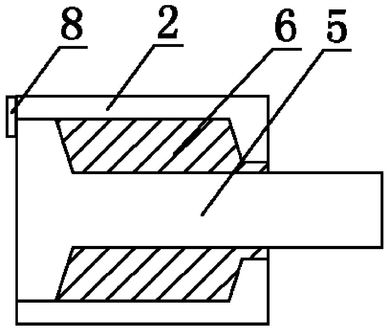
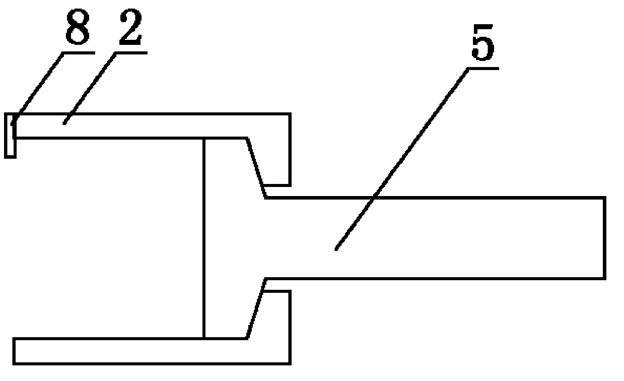
[0019] Embodiment 1: as Figure 1 to Figure 3 In the hydraulic coupler over-temperature protection device shown, the fusible plug 2 is detachably connected to the hydraulic coupler, its cylinder is connected with the hydraulic oil chamber 1, the proximity switch 3 is connected to the mounting bracket 4, and the mounting bracket 4 It can be arranged on the base of the driving device, and the connection between the proximity switch 3 and the bracket 4 and / or the connection between the bracket 4 and the base adopts a detachable connection method, so that the proximity switch 3 and / or the installation bracket 4 are connected to the fusible plug The distance between 2 is adjustable. The sensing head of the proximity switch 3 is located near the side of the fusible plug 2 , and the sensing head of the proximity switch 3 coincides with the central axis of the fusible plug 2 during initial installation. Such as Figure 4 and Figure 5 As shown, in this embodiment, the fusible plug ...

Embodiment 2

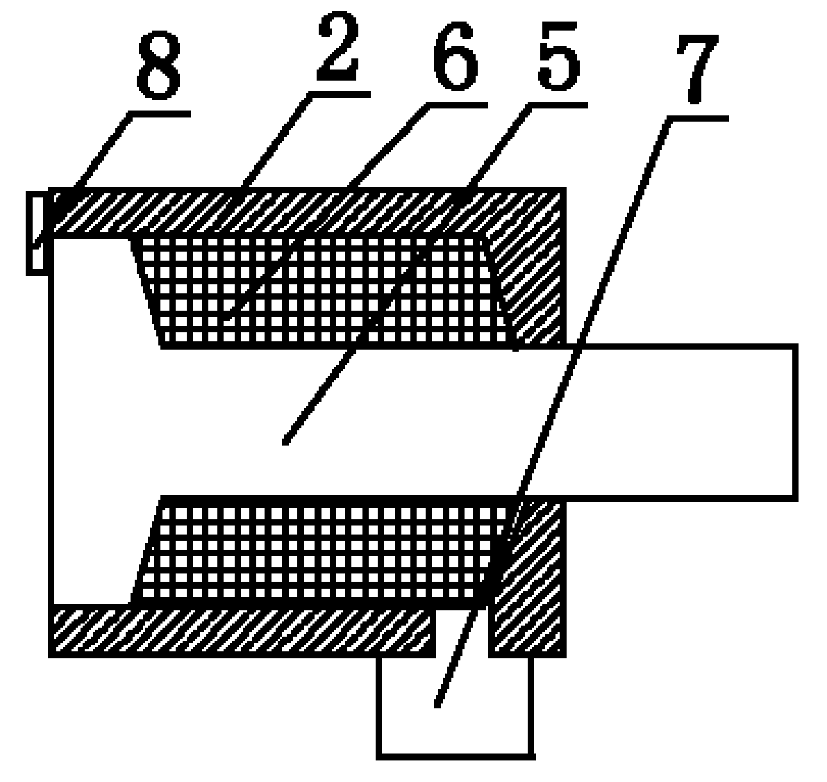
[0022] Embodiment 2: as Figure 1 to Figure 3 In the hydraulic coupler over-temperature protection device shown, the fusible plug 2 is fixedly connected to the hydraulic coupler, its cylinder is connected to the hydraulic oil chamber 1, and the proximity switch 3 is connected to the mounting bracket 4, which can be set On the base of the driving device, the connection between the proximity switch 3 and the bracket 4 and / or the connection between the bracket 4 and the base adopts a detachable connection mode, so that the proximity switch 3 and / or the installation bracket 4 and the fusible plug 2 The distance between them is adjustable. The sensing head of the proximity switch 3 is located near the side of the fusible plug 2 , and the sensing head of the proximity switch 3 coincides with the central axis of the fusible plug 2 during initial installation. Such as Figure 6 and Figure 7As shown, in this embodiment, the fusible plug 2 includes a cylinder fixed on the hydraulic ...


PUM


Abstract

The invention discloses a hydraulic coupler over-temperature protection device and a repairing method thereof. The hydraulic coupler over-temperature protection device comprises a fusible plug (2) and a proximity switch (3), wherein the proximity switch (3) is positioned on one side close to the fusible plug (2); the central axes of the proximity switch and the fusible plug (2) are coincided with each other during initial installation; the fusible plug (2) comprises a cylinder barrel, and a piston and a piston rod (5) which are positioned in the cylinder barrel; the cylinder barrel is partitioned into a rod-including cavity and a rod-free cavity by the piston; the rod-including cavity is communicated with a hydraulic oil cavity (1); the rod-including cavity is filled with fusible metal (6), and is provided with a channel through which a fused fusible metal flows out; when the fusible metal is filled into the rod-including cavity, the distance between piston rod (5) and the proximity switch (3) is larger than a detected distance; and after the fusible metal flows out by fusing, the distance between piston rod (5) and the proximity switch (3) is not greater than the detected distance. During repairing, the fused fusible plug (2) and a fusible alloy to be filled are heated, and the fusible alloy is fused into liquid and then is filled into the fusible plug (2); and after the fusible alloy is cooled and condensed, the device can be used once again.

Description

technical field [0001] The invention relates to the technical field of hydraulic couplings, in particular to an over-temperature protection device for a hydraulic coupling; the invention also relates to a repair method for an over-temperature protection device for a hydraulic coupling. Background technique [0002] The hydraulic coupling is a non-rigid coupling with liquid as the working medium, also known as the hydraulic coupling. The pump wheel and the turbine of the hydraulic coupling form a closed working chamber that can circulate the liquid. The pump wheel is installed on the input shaft, and the turbine is installed on the output shaft. When the power machine (internal combustion engine, electric motor, etc.) drives the input shaft to rotate, the liquid is thrown out by the centrifugal pump wheel. This high-speed fluid enters the turbine and drives the turbine to rotate, transferring the energy obtained from the pump wheel to the output shaft. Finally, the liquid r...

Claims


Application Information

Patent Timeline
Patent Type & Authority Applications(China)
IPC IPC(8): F16H41/24B23P6/00
Inventor 潘杰周泉刘旭姜鑫张行唐亚球
Owner 泰富重工(沙洋)制造有限公司
Why Eureka
Try Eureka