
Repeated connecting rod test fixture

A technology for testing fixtures and connecting rods, which is applied in the direction of measuring devices, measuring instrument components, instruments, etc., to achieve the effects of convenient repeated testing, convenient use, and simple structure

Inactive Publication Date: 2012-12-05
KUSN MAIZHI FIXTURE TECH
View PDF5 Cites 0 Cited by
  • Summary
  • Abstract
  • Description
  • Claims
  • Application Information

AI Technical Summary

Problems solved by technology

[0002] Existing repeatability test fixtures for related components of mobile phones and computer cameras usually use a telescopic rod structure. For parts that move repeatedly along a curve, the telescopic rod structure cannot be used for testing well, or the structure of the telescopic rod needs to be complicated. Therefore, it is difficult to test the performance of components that move repeatedly along the curve

Method used


Image

  • Repeated connecting rod test fixture
  • Repeated connecting rod test fixture
  • Repeated connecting rod test fixture

Examples


Embodiment Construction

[0014] The present invention will be further described below in conjunction with the accompanying drawings.

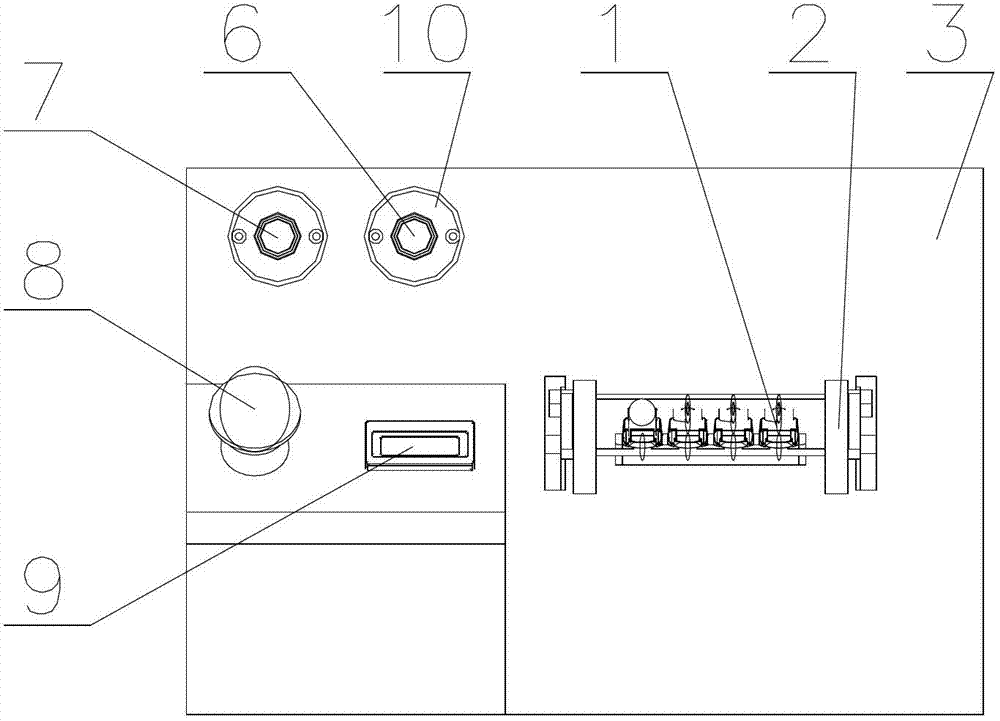
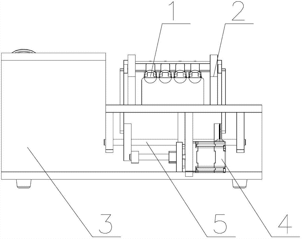
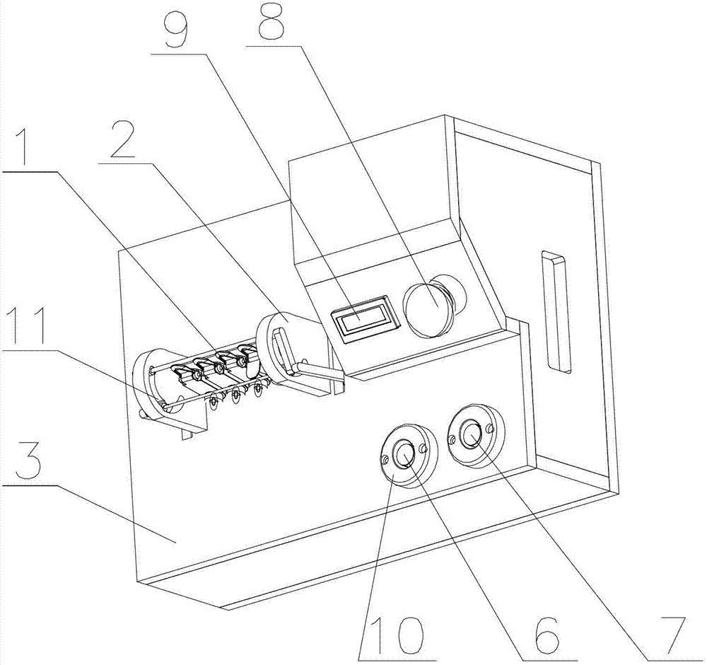
[0015] like figure 1 , figure 2 , image 3 Shown is a repeated connecting rod test fixture, including a bracket 2, a bottom box 3, a connecting rod mechanism 5, and a motor 4. The bracket 2 is provided with a track groove 11 adapted to the movement line of the product, and the motor 4 is installed on the bottom. In the box 3, the bracket 2 is fixed on the bottom box 3, the input end of the linkage mechanism 5 is connected with the output shaft of the motor 4, and the output end of the linkage mechanism 5 is connected with the track groove 11; when the motor 4 rotates, the linkage mechanism 5 is driven The output end of the motor 4 reciprocates along the track groove 11; the start button 6, stop button 7 and emergency stop button 8 of the motor 4 are all arranged on the bottom box 3, and the outside of the start button 6 and the stop button 7 are all provided with bu...


PUM


Abstract

The invention discloses a repeated connecting rod test fixture. The repeated connecting rod test fixture comprises a support, a bottom box, a connecting rod mechanism and an electric motor, wherein the support is provided with a track groove which is in fit with a product motion line, the electric motor is arranged in the bottom box, the support is fixedly arranged on the bottom box, an input end of the connecting rod mechanism is connected with an output shaft of the electric motor, an output end of the connecting rod mechanism is connected with the track groove, and the electric motor drives the output end of the connecting rod mechanism to do reciprocating motion along the track groove when in rotation. According to the repeated connecting rod test fixture disclosed by the invention, the structure is simple, the use is convenient, and repeated tests for curvilinear motion of a product can be conveniently carried out.

Description

technical field [0001] The invention relates to a fixture for repeated connecting rod testing of mobile phones and computer cameras. Background technique [0002] Existing repeatability test fixtures for related components of mobile phones and computer cameras usually use a telescopic rod structure. For parts that move repeatedly along a curve, the telescopic rod structure cannot be used for testing well, or the structure of the telescopic rod needs to be complicated. Therefore, it is difficult to perform performance tests on components that move repeatedly along curves. Contents of the invention [0003] Purpose of the invention: In order to overcome the deficiencies in the prior art, the present invention provides a repetitive connecting rod test jig, which can realize the performance test of the product repeatedly moving along the curve through a simple connecting rod structure. [0004] Technical solution: In order to solve the above-mentioned technical problems, the ...

Claims


Application Information

Patent Timeline
Patent Type & Authority Applications(China)
IPC IPC(8): G01D11/00
Inventor 蔡青春
Owner KUSN MAIZHI FIXTURE TECH
Learn More