Multifunctional electrodeless lamp aging device

An aging device and electrodeless lamp technology, which is applied in the factory adjustment of electric tubes/lamps, etc., can solve the problems of inconvenient use and single function, and achieve the effects of prolonging service life, saving electricity costs, and high aging efficiency

Inactive Publication Date: 2012-12-05
JIANGSU GODLIGHT LIGHTING TECH
View PDF7 Cites 4 Cited by
  • Summary
  • Abstract
  • Description
  • Claims
  • Application Information

AI Technical Summary

Problems solved by technology

The existing electrodeless lamp aging device has a single function, and cannot perform the conversion of impact aging, normal aging and timing aging, and is inconvenient to use

Method used


Image

  • Multifunctional electrodeless lamp aging device

Examples


Embodiment 1

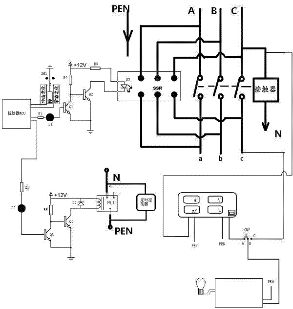
[0015] see figure 1 , the multi-functional electrodeless lamp aging device includes a controller MCU, a solid state relay SSR for controlling the power supply of the electrodeless lamp, a solid state relay SSR driving circuit, and a contact for controlling the power supply of the electrodeless lamp and being in a disconnected state during standby. A device, a contactor drive circuit, a time controller that is electrically connected with the contactor and is used to control the pull-in and disconnection of the contactor according to the start time and duration of the aging of the electrodeless lamp input by the user; the time controller is also connected with the controller The MCU is electrically connected; the controller MCU, the solid-state relay SSR drive circuit and the solid-state relay SSR are electrically connected sequentially; and the controller MCU is electrically connected to the controller MCU for controlling the controller MCU to be in the standby state or to contr...


PUM


Abstract

The invention discloses a multifunctional electrodeless lamp aging device, which comprises a control MCU (Microprogrammed Control Unit), a solid state relay (SSR), an SSR driving circuit, a contactor, a contactor driving circuit, a time controller and a first select switch SW1; when the first select switch SW1 is an impact aging state, the SSR is switched on and off at intervals; when the first select switch SW1 is in a normal aging state, the SSR is switched on, and the contactor is pulled in; the SSR is switched off thereafter; and when the first select switch SW1 is in a stand-by state, a user can select a multifunctional power parameter measuring instrument for working. Due to the adoption of the multifunctional electrodeless lamp aging device, high-speed switch-on and switch-off can be realized at intervals, the phenomenon of fire striking at a pulling-in moment can be avoided for the contactor, and aging operation can be performed at a time interval when the electricity price is low to save electricity charge and energy. Above all, the multifunctional electrodeless lamp aging device has the advantages of simple structure, high reliability, high practicability and high aging efficiency.

Description

technical field [0001] The invention relates to a multifunctional electrodeless lamp aging device, in particular to a multifunctional electrodeless lamp aging device. Background technique [0002] Electrodeless lamps, also called fluorescent lamps, have a filament at each end of the fluorescent lamp. The lamp tube is filled with a small amount of argon and thin mercury vapor. The inner wall of the lamp tube is coated with fluorescent powder. The gas between the two filaments emits ultraviolet rays when conducting electricity, making Phosphors emit soft visible light. Working characteristics of fluorescent lamps: When the lamp starts to ignite, a high voltage is required, and only a small current is allowed to pass through when it is normally lit. At this time, the voltage at both ends of the lamp is lower than the power supply voltage. The two ends of the fluorescent tube are equipped with filaments, and the inner wall of the glass tube is coated with a uniform layer of thi...

Claims


Application Information

Patent Timeline
Patent Type & Authority Applications(China)
IPC IPC(8): H01J9/44
Inventor 庄彦军侯勇敢倪荣国曹明隆
Owner JIANGSU GODLIGHT LIGHTING TECH
Why Eureka
Try Eureka