white light led lighting device

A technology for light-emitting devices and LED chips, which is applied to electrical components, electrical solid-state devices, circuits, etc., can solve the problems of decreased luminous intensity of phosphors, drift of luminous wavelengths of phosphors, and increased operating temperature of devices, so as to avoid the decrease of luminous efficiency of devices. , The effect of alleviating luminous wavelength drift and luminous intensity decrease

Active Publication Date: 2016-03-09
镇江瑞吉光电科技有限公司
View PDF3 Cites 0 Cited by
  • Summary
  • Abstract
  • Description
  • Claims
  • Application Information

AI Technical Summary

Problems solved by technology

The disadvantages of this packaging method are as follows: when the device is working, the heat is too late to dissipate, resulting in an increase in the operating temperature of the device, causing the luminous wavelength of the phosphor to drift, and the luminous intensity of the phosphor will decrease
In addition, when the phosphor is close to the surface of the blue light chip, part of the light emitted by the phosphor will re-enter the chip and be absorbed, resulting in a decrease in the luminous efficiency of the device

Method used


Image

  • white light led lighting device
  • white light led lighting device
  • white light led lighting device

Examples


Embodiment 1

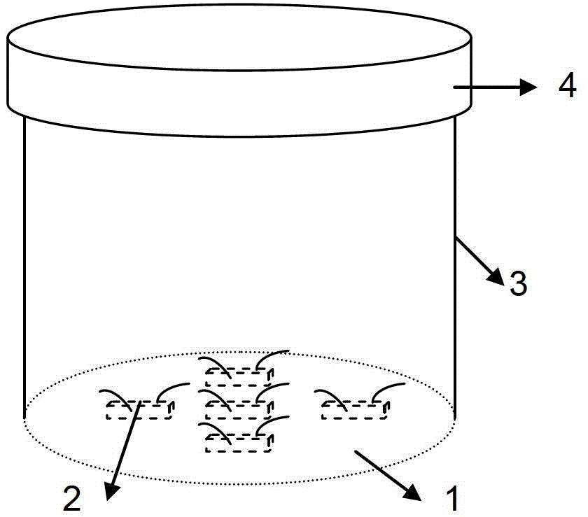
[0051] figure 1 It is a schematic diagram of a white LED lighting device according to Embodiment 1 of the present invention. The white LED lighting device includes: a base 1 , a blue LED chip 2 , a reflector 3 and a substrate 4 . Both ends of the reflector 3 are respectively connected to the base 1 and the substrate 4, the blue LED chip 2 is arranged on the side of the base 1 facing the substrate 4, and the electrode leads of the blue LED chip 2 pass through the base 1, and one surface of the substrate 4 is coated with Phosphor-containing organic coatings.

[0052] As one of the specific embodiments, in order to obtain white light, the phosphor may be LED yellow phosphor. In order to improve the color rendering index of white light, the phosphor can also be a mixture of LED green phosphor and LED red phosphor in any proportion, or a mixture of LED yellow phosphor and a small amount of LED red phosphor. The luminous color, or the color temperature, can be adjusted by adjusti...

Embodiment 2

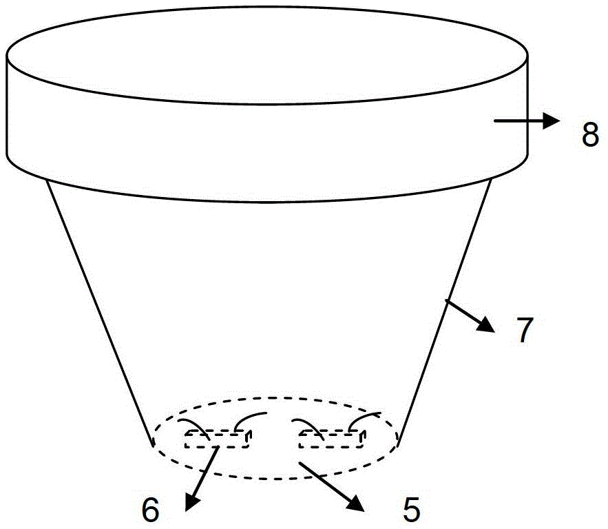
[0060] by figure 2 It is a schematic diagram of the white LED lighting device of Example 2.

[0061] The difference between this embodiment and Embodiment 1 is that the reflector 7 is in the shape of a rounded truncated cone, the base 5 is used as the lower bottom of the rounded truncated truncated shape, and the substrate 8 is used as the upper bottom of the rounded truncated truncated shape.

Embodiment 3

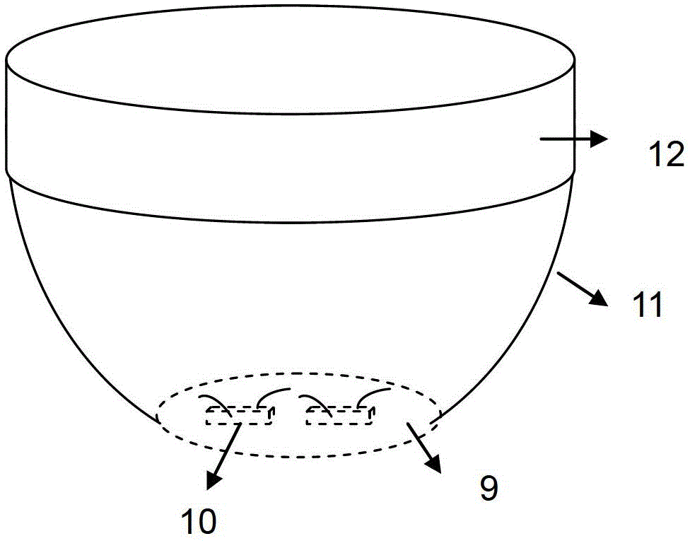
[0063] by image 3 It is a schematic diagram of a white LED lighting device according to Embodiment 3 of the present invention.

[0064] The difference between this embodiment and Embodiment 1 is that the reflector 11 is in the shape of a bowl, the base 9 serves as the bottom of the bowl, and the base plate 12 is located at the mouth of the bowl.


PUM


Abstract

A white LED light-emitting device, comprising a base, a blue LED chip, a reflector and a transparent substrate containing a phosphor coating, the two ends of the reflector are respectively connected to the base and the substrate, and a reflective layer is provided on the internal reflection surface of the reflector, and the blue LED The chip is arranged on the base facing the side of the transparent substrate with phosphor coating, and the electrode leads of the blue LED chip pass through the base; wherein the blue LED chip is a single chip, a group of serial, parallel or mixed chips. The transparent substrate can be planar, or convex, or cylindrical. The present invention uses the blue light emitted by the blue LED chip to irradiate the transparent substrate containing the phosphor coating to obtain white light, which reduces the luminous loss caused by the part of the light excited by the phosphor re-entering the chip and being absorbed, and also alleviates the problem of heat dissipation. There will be no luminous wavelength drift and luminous efficiency decrease due to device heat dissipation problems.

Description

technical field [0001] The invention relates to a white LED lighting device. Background technique [0002] As a new lighting method, white LED is based on the following working principle: LED blue light chip emits blue light to irradiate phosphor (phosphor powder), and phosphor is excited by blue light to emit yellow light, or mixed light of green light and red light, or yellow light. A mixture of light and red light. The light emitted by these phosphors is mixed with part of the blue light emitted by the blue chip to synthesize white light. In common encapsulation technology, the phosphor is evenly cured on the chip surface by mixing with silicone or resin. The disadvantages of this packaging method are as follows: when the device is working, the heat is too late to dissipate, resulting in an increase in the operating temperature of the device, causing the luminous wavelength of the phosphor to drift, and the luminous intensity of the phosphor to decrease. In addition, w...

Claims


Application Information

Patent Timeline
Patent Type & Authority Patents(China)
IPC IPC(8): H01L25/075H01L33/50H01L33/64
CPCH01L2224/48091H01L2924/3025
Inventor 殷江钱志强金正武
Owner 镇江瑞吉光电科技有限公司
Why Eureka
Try Eureka