Light guide plate and backlight module

A light guide plate and light source technology, applied in optics, light guides, light sources, etc., can solve the problems of large color drift over time, reduced luminous efficiency, and low luminous efficiency, and achieve the effect of avoiding the decline of light efficiency and improving light guide efficiency

Active Publication Date: 2012-08-22
TCL CHINA STAR OPTOELECTRONICS TECH CO LTD
View PDF5 Cites 0 Cited by
  • Summary
  • Abstract
  • Description
  • Claims
  • Application Information

AI Technical Summary

Problems solved by technology

[0005] As mentioned above, the fluorescent powder coating method in the prior art mainly has the following disadvantages: First, LEDs will generate a large amount of heat during the light emitting process, and the accumulation of heat will lead to a higher temperature of the phosphor powder coating part, but the phosphor powder does not Accelerated aging due to high temperature resistance; in addition, the reflection and absorption loss of phosphor to light also reduces the luminous efficiency of LED
Therefore, LEDs with this coating method have disadvantages such as rapid decline in luminous efficacy, large color drift over time, and low luminous efficiency.

Method used


Image

  • Light guide plate and backlight module
  • Light guide plate and backlight module
  • Light guide plate and backlight module

Examples


Embodiment Construction

[0024] In order to make the above-mentioned purposes, features and advantages of the present invention more obvious and understandable, the preferred embodiments of the present invention will be specifically cited below, together with the accompanying drawings, for a detailed description as follows:

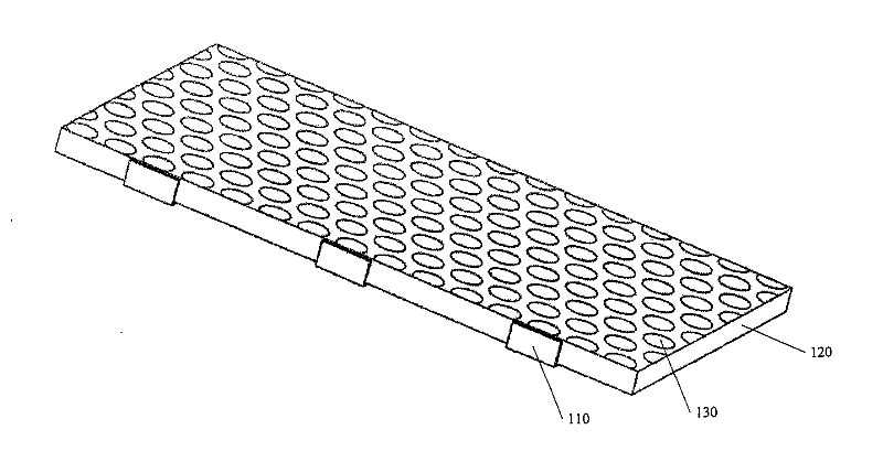
[0025] Such as Figure 4 Shown is a schematic diagram of the overall structure of the edge-lit backlight module in the present invention. The edge-lit backlight module includes several LEDs 210 and a light guide plate 220 . Wherein, the light guide plate 220 includes a bottom surface, a light incident surface and a light exit surface, the light exit surface is opposite to the bottom surface, and the bottom surface includes a plurality of dots 230 . Optionally, the light-emitting surface is connected to the light-incoming surface. The LED 210 is placed on the side of the light guide plate 220 , opposite to the light incident surface, and the light emitted by the LED 210 is incid...


PUM

PropertyMeasurementUnit
diameteraaaaaaaaaa

Abstract

The invention provides a light guide plate and a backlight module. The light guide plate comprises a bottom surface, a light entering surface and a light emitting surface, wherein the light emitting surface is arranged opposite to the bottom surface; the bottom surface comprises a plurality of mesh points; the mesh points comprise fluorescent powder; and scattered particles are added selectively. Phenomena such as color offset caused by accelerated aging of the fluorescent powder which is close to a light-emitting diode (LED) chip and reduction in light emitting efficiency are avoided.

Description

【Technical field】 [0001] The invention relates to the technical field of liquid crystal display, in particular to a light guide plate and a backlight module including the light guide plate. 【Background technique】 [0002] Since the liquid crystal itself of the liquid crystal display panel does not have light-emitting characteristics, in order to achieve the display effect, it is necessary to provide a light source device for the liquid crystal display panel, such as a backlight module, whose function is to provide a surface light source with sufficient brightness and uniform distribution to the liquid crystal display panel. [0003] In the prior art, the backlight module includes a light source, a light guide plate and some other necessary parts. The function of the light guide plate is to guide the transmission direction of the light so that the light is uniformly emitted from the light-emitting surface of the light guide plate. The light source is, for example, a light-emit...

Claims


Application Information

Patent Timeline
Patent Type & Authority Patents(China)
IPC IPC(8): G02B6/00G02F1/13357F21S8/00F21V13/00F21Y101/02
CPCG02B6/00G02B6/0043F21S8/00F21V13/00
Inventor 黄建发林博瑛
Owner TCL CHINA STAR OPTOELECTRONICS TECH CO LTD
Why Eureka
Try Eureka