Switched reluctance motor

A technology of switched reluctance motors and yokes, applied in magnetic circuits, synchronous machines, electromechanical devices, etc., can solve problems such as core loss

Inactive Publication Date: 2012-12-05
SAMSUNG ELECTRO MECHANICS CO LTD
View PDF9 Cites 28 Cited by
  • Summary
  • Abstract
  • Description
  • Claims
  • Application Information

AI Technical Summary

Problems solved by technology

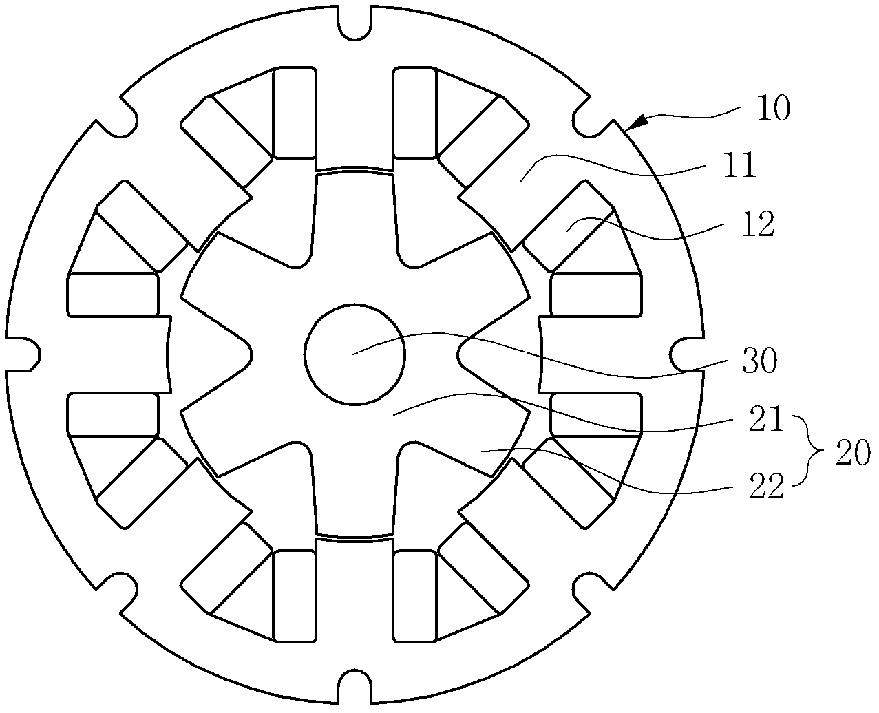
[0012] However, the switched reluctance motor according to the prior art may suffer from core loss due to the path of the magnetic flux passing through both the stator 10 and the rotor 20

Method used


Image

  • Switched reluctance motor
  • Switched reluctance motor
  • Switched reluctance motor

Examples


Embodiment Construction

[0040] The above and other objects, features and advantages of the present invention will be more clearly understood through the following detailed description in conjunction with the accompanying drawings. In the specification, reference numerals are added to components throughout the drawings, and it should be noted that the same reference numerals designate the same components even if the components appear in different drawings. In addition, words "first", "second", "a surface" and "another surface" etc. in the specification are used to distinguish one component from another, but the component is not limited to the interpretation of the above words. In describing the present invention, detailed descriptions of related known functions or structures will be omitted so as not to obscure the gist of the present invention.

[0041] Hereinafter, preferred embodiments of the present invention will be described in detail with reference to the accompanying drawings.

[0042] Figu...


PUM


Abstract

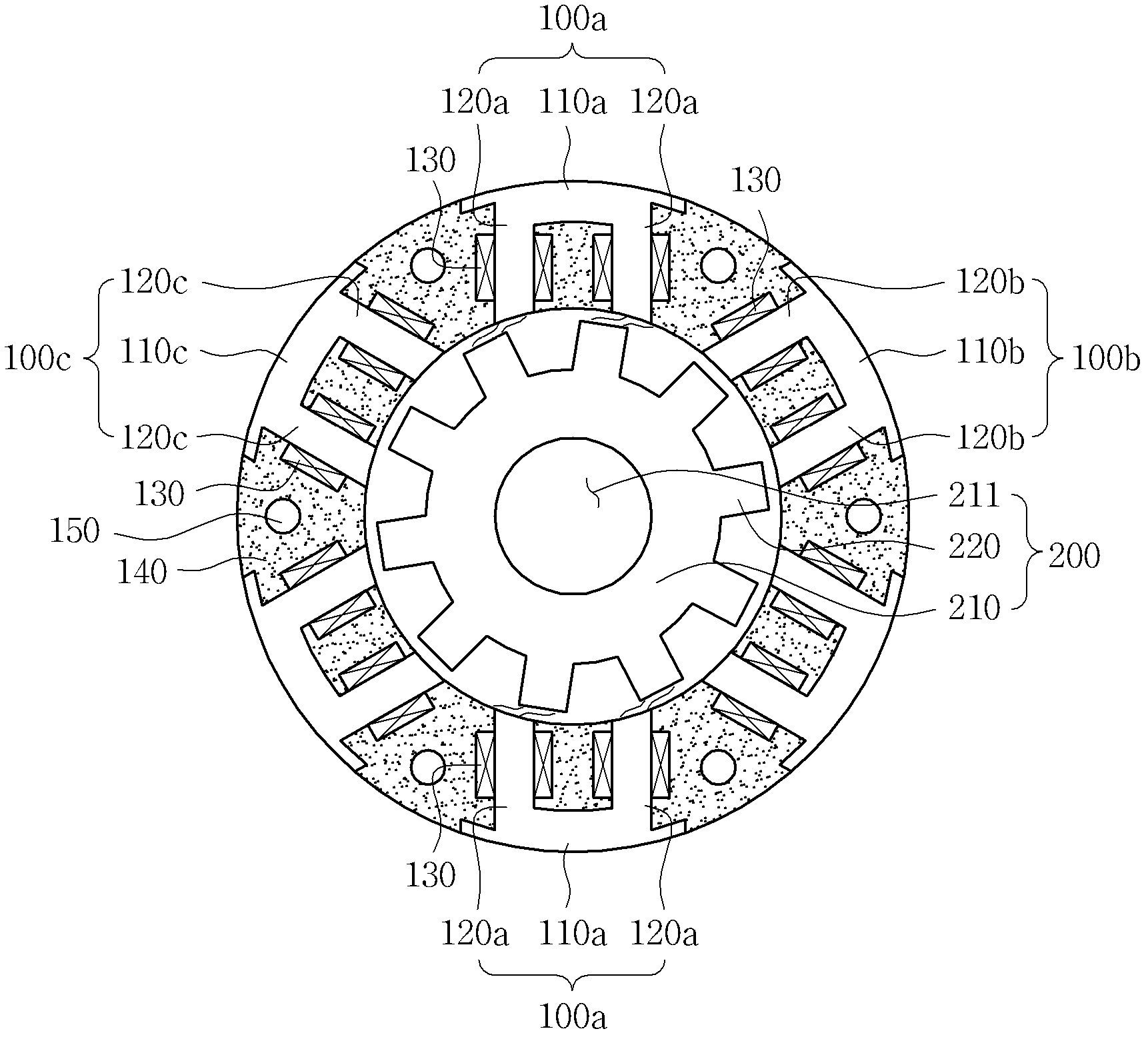
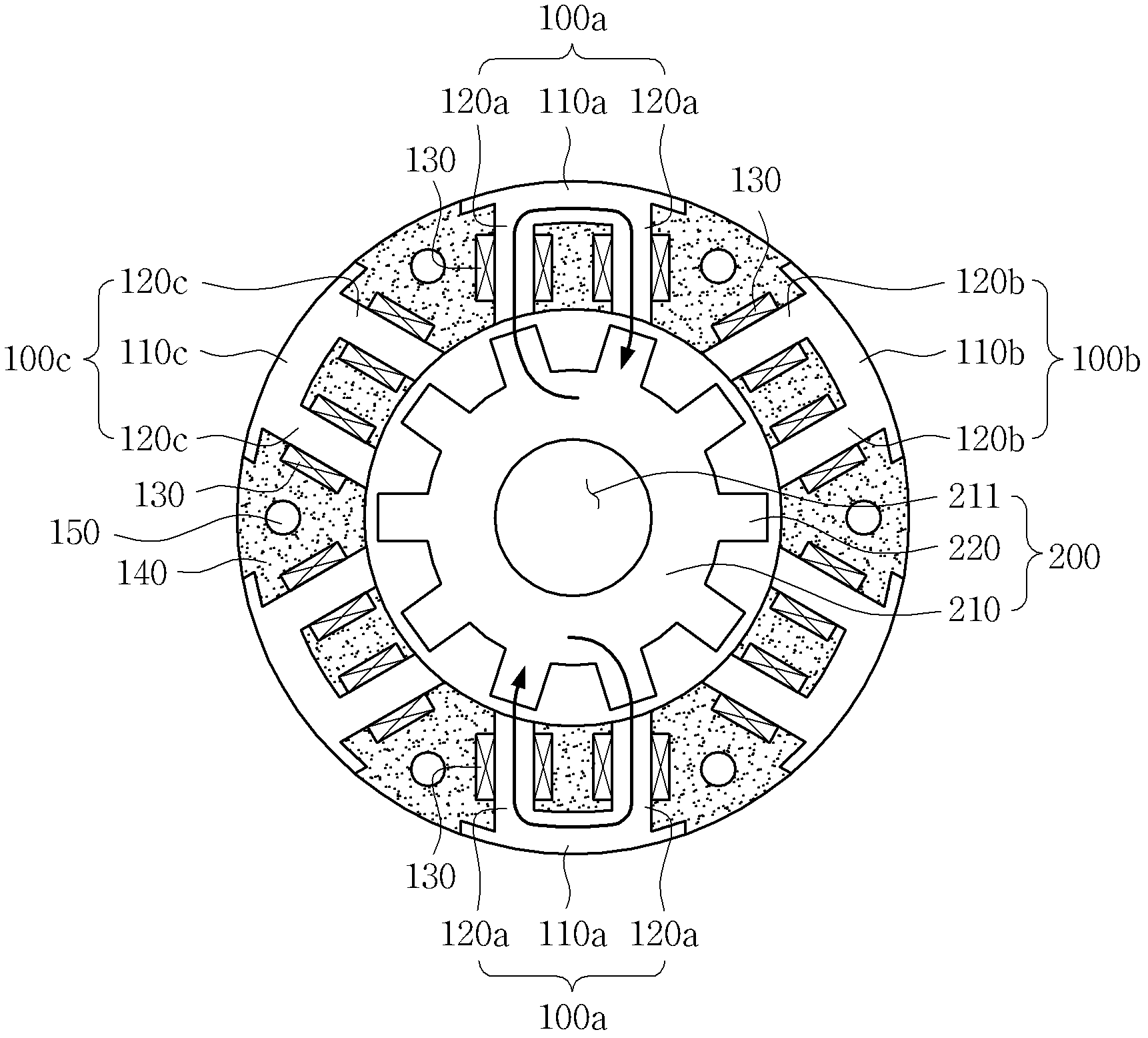
Disclosed herein is a switched reluctance motor, including: a rotor provided with a plurality of salient poles protruded along an outer peripheral surface thereof; and a stator including a plurality of stator cores in a pi ([pi]) shape that have the rotor rotatably accommodated therein, are opposite to the plurality of salient poles, and have coils wound therearound, wherein a magnetic flux path is formed along the stator cores in the pi shape and the salient pole opposite thereto.

Description

[0001] Cross References to Related Applications [0002] This application claims the priority of Korean Patent Application No. 10-2011-0053434, filed June 2, 2011, entitled "SWITCHED RELUCTANCE MOTOR", the entire contents of which are hereby Incorporated into this application by reference. technical field [0003] The invention relates to a switched reluctance motor. Background technique [0004] Recently, the demand for motors has greatly increased in various industries such as automotive, aerospace, military, and medical equipment. In particular, switched reluctance motors (herein referred to as SR motors) have beneficially become a new option as the cost of motors using permanent magnets has increased due to rapidly increasing prices of rare earth materials. [0005] The driving principle of the switched reluctance motor is to rotate a rotor using a reluctance torque generated by a change in reluctance. [0006] Usually, such as figure 1 As shown, the switched relucta...

Claims


Application Information

Patent Timeline
Patent Type & Authority Applications(China)
IPC IPC(8): H02K29/00H02K1/24H02K1/14
CPCH02K1/141H02K19/103H02K37/02H02K1/14H02K9/22H02K9/223
Inventor 金昶成崔昌焕裴汉京李根洪
Owner SAMSUNG ELECTRO MECHANICS CO LTD
Why Eureka
Try Eureka