
Dielectric chip antennas

A technology of dielectric and dielectric blocks, applied in antennas, resonant antennas, loop antennas, etc., can solve problems such as not working well

Active Publication Date: 2012-12-05
MICROSOFT TECH LICENSING LLC
View PDF17 Cites 10 Cited by
  • Summary
  • Abstract
  • Description
  • Claims
  • Application Information

AI Technical Summary

Problems solved by technology

For example, a chip antenna works well in the middle of one edge of the mounting board, but not in a corner, or vice versa

Method used


Image

  • Dielectric chip antennas
  • Dielectric chip antennas
  • Dielectric chip antennas

Examples


Embodiment Construction

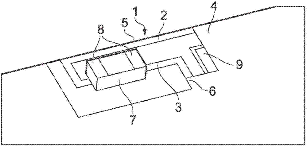
[0035] In the first embodiment of the present invention, as figure 1 As shown, the main radiating antenna comprises a conductive loop 1 formed by conductive tracks 2 , 3 formed on a PCB substrate 4 and grounded at two ends 5 , 6 . Loop 1 is interrupted by a dielectric chip capacitor 7 towards the center of loop 1 . The inductance of loop 1 and the capacitance of the metallized dielectric chip cause a resonance at the desired operating frequency. The metallization 8 of the dielectric chip 7 is similar to that disclosed in US2003 / 0222827 or WO2006 / 000631, but the way the device is deployed on the mounting board 4 and how the device works as an antenna is very different. The main radiating antenna is a parasitic device which is excited by a separate feeding antenna 9 . In this first embodiment, the feeding antenna 9 is also a loop powered at one end and grounded at the other end. exist figure 1 In the embodiment shown, the conductive strips 2, 3 are respectively connected at ...


PUM


Abstract

There is disclosed an antenna arrangement having a parasitic conductive loop (1) and at least one active radiating element (9). The conductive loop (1) comprises first and second electrically conductive passive radiating elements (2, 3) each with first and second ends. The first ends of the passive radiating elements are each connected to ground, and the second ends of the radiating elements are each connected respectively to mutually discrete metalized surface regions (8) of a dielectric block (7). The at least one active radiating element (9) is not conductively connected to the passive radiating elements (2, 3). The passive radiating elements (2, 3) are configured to be fed parasitically by the at least one active radiating element (9). The antenna arrangement has excellent resistance to detuning and can be located in different regions of a PCB substrate without significantly affecting performance. Further, the antenna is small in size and may be arranged for dual band operation.

Description

technical field [0001] Embodiments of the invention relate to surface mount dielectric chip antennas with improved stability against detuning. Background technique [0002] Electrically, surface-mounted dielectric chip antennas are small antennas typically used on small platforms such as mobile communication devices. They feature a block of dielectric material mounted on a non-grounded area of ​​the circuit board. Conductive tracks are printed on the dielectric block. The antenna is formed from this conductive strip rather than the dielectric material itself. [0003] Typically, dielectric chip antennas have a cubic or hexahedron-like shape, but other shapes are also possible. Typically, a surface mount chip antenna is characterized by at least two conductive electrodes (usually three), a feed electrode, a ground electrode and a radiating segment. In the absence of a ground electrode, a unipolar design is sometimes used; in this case, pads with no electrical function can...

Claims


Application Information

Patent Timeline
Patent Type & Authority Applications(China)
IPC IPC(8): H01Q1/38H01Q7/00H01Q9/30H01Q5/00H01Q5/10H01Q5/385H01Q5/40
CPCH01Q7/00H01Q9/30H01Q5/0065H01Q5/0072H01Q5/385H01Q5/40H01Q1/243H01Q1/38H01Q5/20H01Q23/00
Inventor 马克·哈珀
Owner MICROSOFT TECH LICENSING LLC
Features
  • Generate Ideas
  • Intellectual Property
  • Life Sciences
  • Materials
  • Tech Scout
  • Unparalleled Data Quality
  • Higher Quality Content
  • 60% Fewer Hallucinations
Learn More