Efficient grinding mechanism for vertical roller mill

A vertical roller mill, high-efficiency technology, applied in grain processing and other directions, can solve the problems of low grinding efficiency, long production cycle, complicated manufacturing, etc., and achieve the effects of improving grinding efficiency, short maintenance cycle, and simple processing

Inactive Publication Date: 2012-12-12
扬州中材机器制造有限公司
View PDF0 Cites 3 Cited by
  • Summary
  • Abstract
  • Description
  • Claims
  • Application Information

AI Technical Summary

Problems solved by technology

[0003] The grinding rollers of the traditional vertical roller mill are large rollers of the same size, and each grinding roller undertakes the functions of fine crushing, compaction and grinding. When there are lump materials, the upper layer of larger material blocks will turn over and leave the grinding area, and the grinding roller only crushes, compacts and grinds the lower layer of smaller materials, so the grinding efficiency is low
[0004] Traditional groove-shaped grinding discs can only be surfacing for wear-resistant treatment. Not only is the manufacturing complicated, the production cycle is long, and the requirements for the material of the grinding disc are also high. Because the surface of the traditional grinding disc needs to be surfacing with a wear-resistant layer, the grinding disc must be cast Steel, the casting process is complicated and difficult (the fluidity of molten steel is poor during casting, and the production of large steel castings is difficult)
However, the machining of the grinding disc of the groove is complicated
[0005] At present, the grinding mechanisms of domestic vertical roller mills are mainly spherical grinding rollers and groove-shaped grinding discs, which are complex in shape, difficult to manufacture and high in cost, difficult and expensive to repair after wear, and low in grinding efficiency.
At the same time, due to the difficulty in repairing the grinding mechanism after wear and tear, the repair time is long, resulting in a low operating rate of the vertical roller mill
These shortcomings have affected the operating rate of the entire cement production line, affecting the operating rate and benefits of the cement production line

Method used


Image

  • Efficient grinding mechanism for vertical roller mill
  • Efficient grinding mechanism for vertical roller mill

Examples


Embodiment Construction

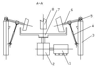
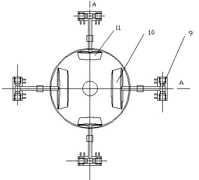
[0019] As shown in the accompanying drawings, the motor 1 drives the reducer 2 to run, and the grinding disc 7 connected to the output shaft of the reducer 2 makes a rotary motion at the same time. The material falls from the feeding pipe 8 to the center of the grinding disc 7, moves along the surface of the grinding disc 7 to the edge under the action of centrifugal force, and forms a material layer at the outer edge of the grinding disc surface. The rotary shaft 5 and the grinding roller shaft 6 installed in the bearing seat at the upper end of the column 3 together form a rocker arm, and the hydraulic (pneumatic) spring 4 controls the large grinding roller 10 and the small grinding roller through the rocker arm composed of the rotary shaft 5 and the grinding roller shaft 6. 11 Apply grinding pressure, the grinding disc 7 drives the grinding rollers to rotate along their respective grinding roller shafts 6 through the material layer, and the grinding disc and grinding rollers...


PUM


Abstract

The present invention relates to an efficient grinding mechanism for a vertical roller mill. The efficient grinding mechanism comprises a drive mechanism, wherein the drive mechanism is connected with a grinding table, the upper part of the grinding table is provided with a feeding tube, a plurality of grinding rollers are arranged on the circumferential edge of the grinding table, the grinding rollers are divided into large grinding rollers and small grinding rollers, and the large grinding rollers and the small grinding rollers are arranged on the circumferential edge of the grinding table in a staggered manner. The present invention provides an efficient grinding mechanism for a vertical roller mill, wherein the efficient grinding mechanism has characteristics of high grinding efficiency, simple structure and easy maintenance.

Description

technical field [0001] The invention relates to a high-efficiency grinding mechanism for a vertical roller mill, belonging to the field of high-efficiency grinding mechanisms. Background technique [0002] The vertical roller mill integrates the functions of grinding, drying, classification (powder selection) and conveying, and has the advantages of high efficiency, low energy consumption, low abrasion, high operation rate, compact structure, small site and space occupation, low noise, The fineness of the product is easy to adjust and other obvious advantages, and it is more and more widely used in the grinding and ultrafine grinding of cement (raw meal, coal, clinker), metallurgical slag, materials, chemical industry and other materials. [0003] The grinding rollers of the traditional vertical roller mill are large rollers of the same size, and each grinding roller undertakes the functions of fine crushing, compaction and grinding. When there is a large block of material,...

Claims


Application Information

Patent Timeline
Patent Type & Authority Applications(China)
IPC IPC(8): B02C15/04
Inventor 杨生强
Owner 扬州中材机器制造有限公司
Why Eureka
Try Eureka