Supercharge Your Innovation With Domain-Expert AI Agents!

Device and method used for cleaning chamber before etching process

A cleaning and process technology, applied in cleaning methods and utensils, chemical instruments and methods, etc., can solve problems such as poor products, increase cleaning costs, and reduce fault tolerance of production lines, so as to increase process time, extend maintenance cycles, and reduce products. bad effect

Active Publication Date: 2012-12-12
BOE TECH GRP CO LTD +1
View PDF4 Cites 4 Cited by
  • Summary
  • Abstract
  • Description
  • Claims
  • Application Information

AI Technical Summary

Problems solved by technology

[0005] One of the main reasons for particle pollution is that the reaction products deposited on the inner wall of the chamber fall off due to strong pressure changes in the chamber during the process. In the existing process, the BT step only removes the natural oxide layer on the surface before etching. Pre-treatment, this treatment method cannot effectively optimize the chamber environment, that is, it cannot clean the particle contamination inside the chamber, which shortens the chamber maintenance cycle, reduces the fault tolerance of the production line, and may cause product damage caused by particle contamination. bad
Existing cleaning devices are often specially designed additional cleaning equipment, which increases additional material consumption costs and increases cleaning costs

Method used


Image

  • Device and method used for cleaning chamber before etching process
  • Device and method used for cleaning chamber before etching process

Examples


Embodiment 1

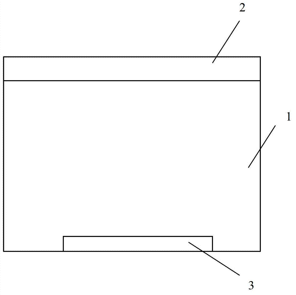
[0030] Embodiment 1 of the present invention provides a device for cleaning the substrate before the etching process, which is used to optimize the environment in the chamber to be dry-etched and reduce particle pollution in the chamber. The device is a cuboid vacuum The chamber includes a chamber body 1 for placing and transferring an array substrate 3 . The vacuum chamber also includes a chamber cover 2 arranged on the chamber body 1, the chamber cover 2 is an insulating material, and the device also includes liftable pillars (not shown) located in the chamber body 1 shown), a reaction table (not shown) located in the chamber body 1 for absorbing the substrate. The chamber has a length of 2700mm-2800mm and a width of 2400mm-2500mm. Preferably, the chamber has a length of 2700mm and a width of 2400mm.

[0031] The structure of the device in this embodiment is simple, and it can be used to clean the internal environment of the chamber itself before dry etching without adding ...

Embodiment 2

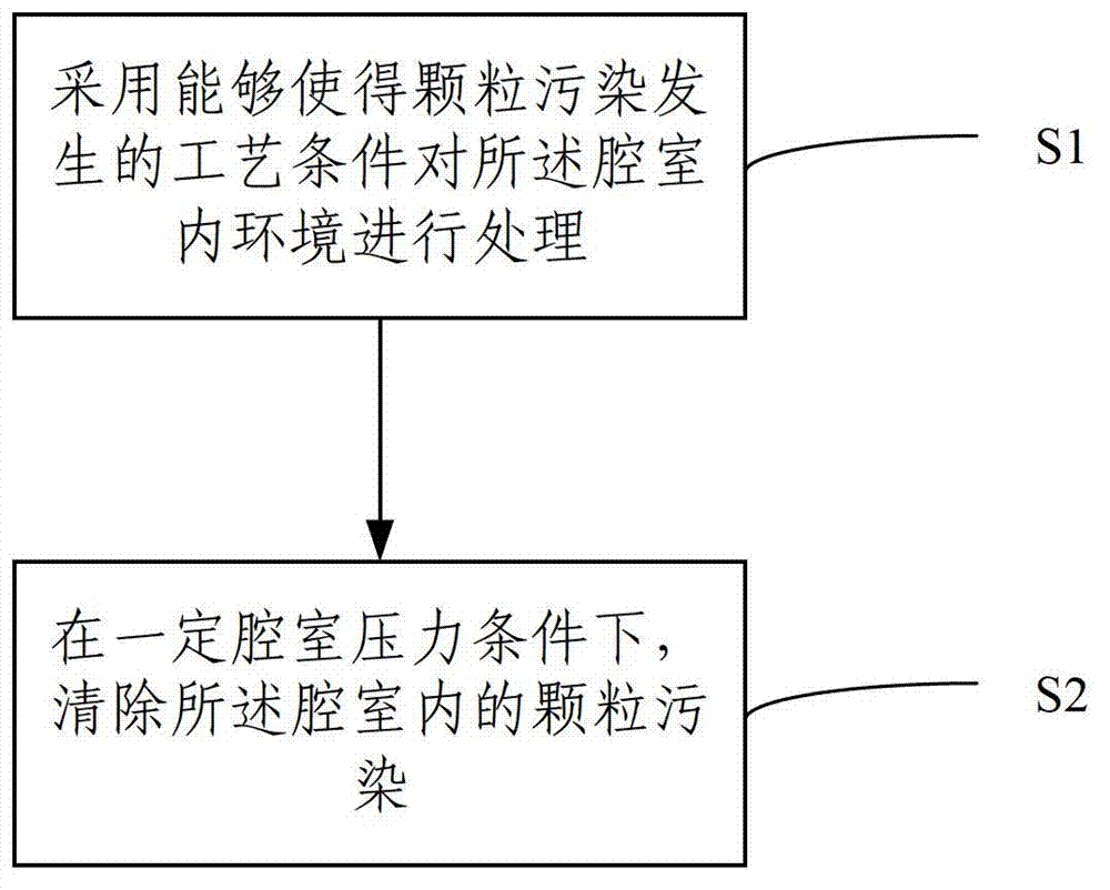
[0033] Embodiment 2 of the present invention also provides a method for cleaning a chamber using the device described in Embodiment 1, including two steps:

[0034] S1. The environment inside the chamber is treated by adopting process conditions where particle pollution is likely to occur. Specifically, by setting the pressure of the chamber, before the array substrate enters the chamber, an aggravated condition of particle pollution that easily induces the reaction product on the inner wall of the chamber to fall off is formed.

[0035] The process conditions of step S1 are: chamber pressure 5-200mt, electrode power 5000-18000W, reaction gas selected from O 2 、CL 2 , SF 6 , He or a combination of several, the total gas flow is 5000-20000 sccm.

[0036] In a further solution, the process conditions of step S1 are: chamber pressure 5-100mt, electrode power 7000-16000W, total gas flow rate 8000-15000sccm.

[0037] S2, removing particle pollution. Specifically, ultra-low cha...


PUM


Abstract

The invention relates to the technical field of a dry etching process in an array substrate production process and discloses a device used for cleaning a substrate before etching process. The device is a chamber and comprises a chamber body and is used for holding and transmitting the substrate. The invention also provides a method for cleaning the substrate before the etching process. The device designed by the invention can be used for cleaning the inner environment of the chamber before the dry etching, so that the influence possibly caused on the array substrate properties by particle pollution can be removed to a large extent.

Description

technical field [0001] The invention relates to the technical field of dry etching process in the production process of array substrates, in particular to a device and method for cleaning a chamber before the etching process. Background technique [0002] At present, in the TFT field, the size of the glass substrate is getting bigger and bigger, and the corresponding chamber is getting bigger and bigger, so the control of particle pollution is becoming more and more difficult. At the same time, due to the larger size of the unit panel, ultra-high resolution (4000* 2000), the development and application of technologies such as in-cell touch screen and GOA (Gate On Array), the impact of particle pollution on product yield and technology development and design has become increasingly prominent. [0003] In the dry etching process, defects such as disconnection and short circuit caused by particle pollution are the key reasons affecting the final yield of the product, and the co...

Claims


Application Information

Patent Timeline
Patent Type & Authority Applications(China)
IPC IPC(8): B08B7/00
Inventor 丁向前孙亮白金超李梁梁刘耀
Owner BOE TECH GRP CO LTD
Features
  • R&D
  • Intellectual Property
  • Life Sciences
  • Materials
  • Tech Scout
  • Unparalleled Data Quality
  • Higher Quality Content
  • 60% Fewer Hallucinations
Learn More