Transmission device of top cross 45-degree continuous rolling machine unit

A transmission device and continuous rolling technology, which is applied to the driving device for metal rolling mills, metal rolling, metal rolling, etc., can solve the problems of inconvenient maintenance, and achieve the effect of convenient maintenance and good working environment

Active Publication Date: 2012-12-12
BEIJING JINGCHENG RUIXINCHANGCAI ENG TECH
View PDF6 Cites 3 Cited by
  • Summary
  • Abstract
  • Description
  • Claims
  • Application Information

AI Technical Summary

Problems solved by technology

[0006] In order to solve the problems of inconvenient maintenance caused by the installation of the transmission device of the bar and wire continuous rolling unit in the prior art under the water-cooled box on the exit side of the rolling produc

Method used


Image

  • Transmission device of top cross 45-degree continuous rolling machine unit
  • Transmission device of top cross 45-degree continuous rolling machine unit
  • Transmission device of top cross 45-degree continuous rolling machine unit

Examples


Example Embodiment

[0081] Example 1

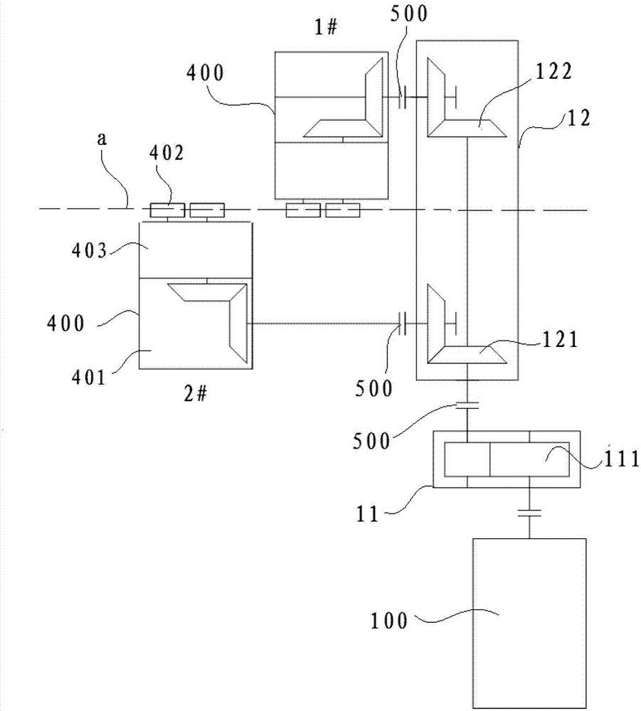
[0082] Such as image 3 As shown, in this embodiment, the transmission device of the top cross 45° continuous rolling mill unit of the present invention is used to provide power for the top cross 45° continuous rolling mill with two stands of 1# and 2# stands.

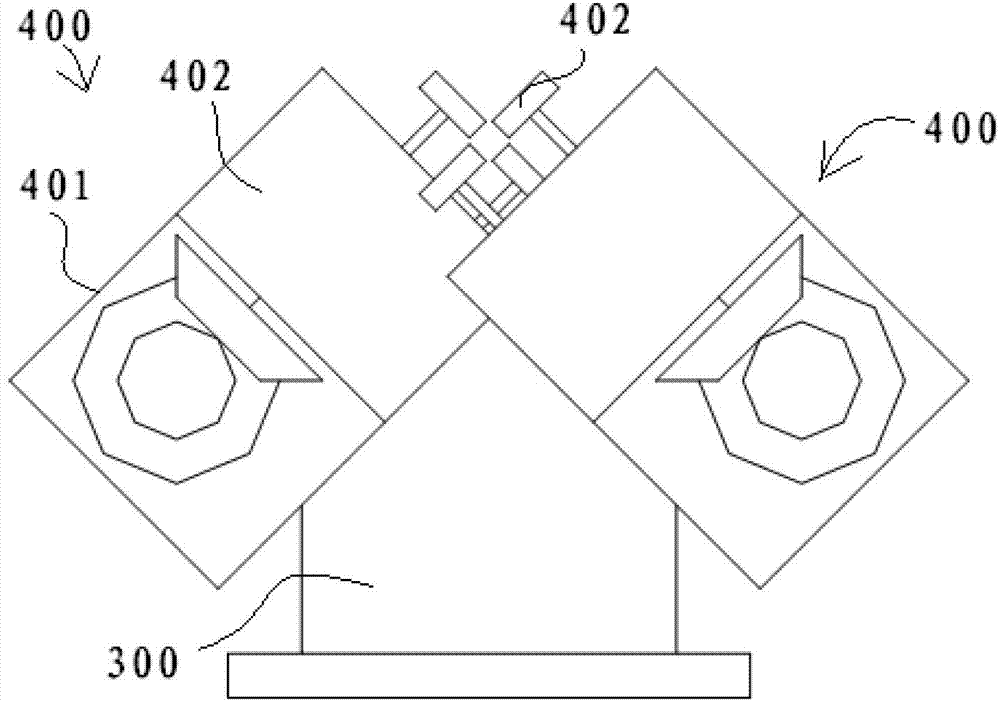
[0083] The 1# and 2# stands of the top cross 45° continuous rolling mill adopt the top cross 45° arrangement, and they are set at 90° to each other. The driving motor 100 is arranged on the side of the rolling centerline a of the top-crossing 45° continuous rolling mill, and the output shaft of the driving motor 100 is perpendicular to the rolling centerline a, and the input shaft of the speed increasing box 11 and the output of the driving motor 100 The shafts are coaxially connected by a coupling 500. The output shaft of the speed increaser and the input shaft of the bevel gear distribution box 12 are connected by a coupling 500. The two output shafts of the bevel gear distribution box 12 are respective...

Example Embodiment

[0089] Example 2

[0090] Such as Figure 4 As shown, the difference between embodiment 2 and embodiment 1 is that the transmission of the top cross 45° continuous rolling mill in this embodiment eliminates the speed increasing box 11, and the output shaft of the driving motor 100 is directly connected to the bevel gear distribution box 12. The input shaft is connected by a coupling 500.

Example Embodiment

[0091] Example 3

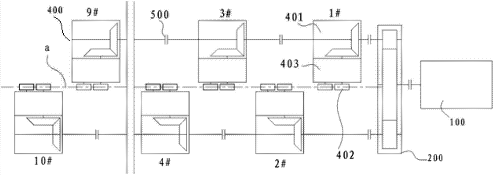
[0092] Such as Image 6 As shown, the top cross 45° continuous rolling mill in this embodiment includes a rolling mill with a total of four stands of 1# stand, 2# stand, 3# stand and 4# stand and two sets of the present invention The transmission device of the top cross 45° continuous rolling mill. In order to ensure that the four racks have the smallest and the same spacing, of the two sets of transmission devices of the top cross 45° continuous rolling mill, one set of the transmission device is set at the entrance side of the top cross 45° continuous rolling mill to drive 1# machine Frame and 3# frame, another set of the transmission device is set on the exit side of the top cross 45° continuous rolling mill, and drive 2# frame and 4# frame.

[0093] In this embodiment, the gear ratio configuration scheme of each gear pair is the same as that of the first embodiment.


PUM


Abstract

The invention provides a transmission device of a top cross 45-degree continuous rolling machine unit. The transmission device comprises a reversing speed changing distribution device provided with two output shafts, rotating center lines of the two output shafts are both arranged perpendicular to the rotating center line of an input shaft, the rotating center line of the input shaft is perpendicular to the rolling center line of the top cross 45-degree continuous rolling machine unit, and the two output shafts are respectively connected with input shafts of a pair of driven bevel gear boxes of an adjacent machine frame. The transmission device further comprises a driving motor arranged on one side of the rolling center line of the top cross 45-degree continuous rolling machine unit, the rotating center line of an output shaft of the driving motor is arranged perpendicular to the rolling center line of the top cross 45-degree continuous rolling machine unit, and the output shaft is connected with the input shaft of the reversing speed changing distribution device. In the transmission device of the top cross 45-degree continuous rolling machine unit, the driving motor is arranged on one side of the rolling center line and is good in working environment and convenient to maintain.

Description

Technical field [0001] The invention relates to a transmission device for a top cross 45° continuous rolling unit, which is suitable for finishing and pre-finishing rolling units of bars and wire rods, and belongs to the field of steel rolling machinery. Background technique [0002] The metal wire rod needs to be rolled after casting the blank, and usually requires multiple sets of rolling mills for continuous rolling, and the cross section of the wire rod is also continuously reduced. In recent years, high-speed wire rod continuous rolling mills have widely adopted top cross 45° continuous rolling mills as finishing mills and pre-finishing mills. Such as figure 1 with figure 2 As shown, the existing high-speed wire rod top cross 45° continuous rolling mill as a finishing mill usually includes a base and 10 racks fixed on the base. The rolls of the 10 racks form a top cross 45° with the horizontal rolling centerline. ° Alternate arrangement. Such as figure 1 As shown, the tra...

Claims


Application Information

Patent Timeline
IPC IPC(8): B21B35/12
Inventor 邓华容陈南宁刘炜陈立坤范思石
Owner BEIJING JINGCHENG RUIXINCHANGCAI ENG TECH
Why Eureka
Try Eureka