

Horizontal lathe device with chuck capable of being clamped and released automatically
A horizontal lathe and automatic clamping technology, applied in auxiliary devices, accessories of tool holders, turning equipment, etc., can solve the problems of low production efficiency, prone to failure, complex structure, etc., and achieve simple structure, high production efficiency, Universal effect
Inactive Publication Date: 2012-12-12
卢修卫
View PDF0 Cites 0 Cited by
- Summary
- Abstract
- Description
- Claims
- Application Information
AI Technical Summary
Problems solved by technology
[0003] The object of the present invention is to provide a horizontal lathe device for automatically clamping and releasing the chuck. This horizontal lathe can not only overcome the low production efficiency defects of the existing common horizontal lathes, but also can Overcome the defects of motorized chuck horizontal lathes, such as complex structure, prone to failure, unsuitable for cylindrical workpieces, and poor versatility
Method used
View moreImage
Smart ImageViewing Examples

Examples
Embodiment Construction
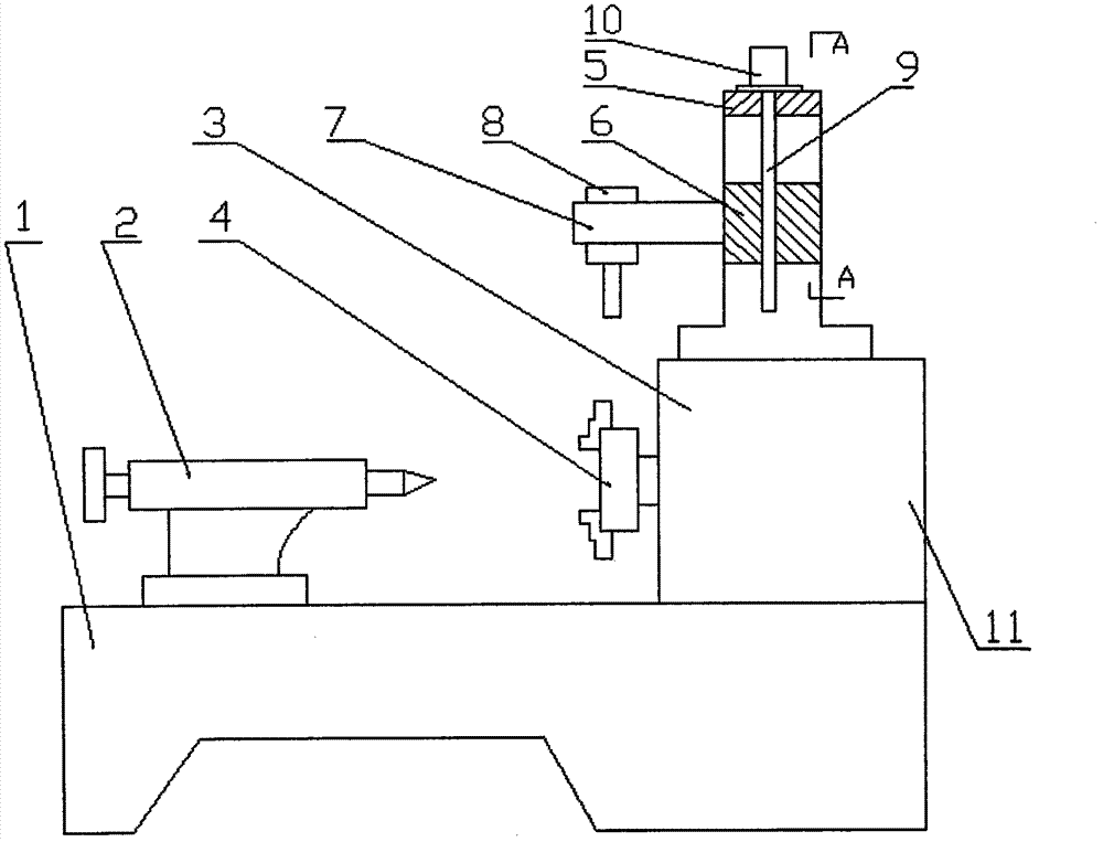
[0009] The lathe seat 1, the tailstock 2, the headstock 3 and the chuck 4 are combined to form a horizontal lathe, the portal column 5 is fixed and installed on the headstock 3 with bolts, and the slider 6 is installed on the opening of the portal column 5. In the middle, the cantilever 7 is fixedly connected with the slider 6, the air wrench 8 is installed and fixed on the cantilever 7, the air motor 10 is installed and fixed on the top of the portal column 5, and the upper end of the lead screw 9 is fixedly connected with the output shaft of the air motor 10, The other end is connected with the slide block 6 through threads.
Login to View More PUM
 Abstract
Disclosed is a horizontal lathe device with a chuck capable of being clamped and released automatically. The horizontal lathe device is characterized in that a lathe seat, a tailstock, a headstock and the chuck are combined to form a horizontal lathe, a gate-type upright column is fixedly mounted on the headstock, a slider is mounted in the middle of an opening of the gate-type upright column, a cantilever is fixedly connected with the slider, a pneumatic lever is fixedly mounted on the cantilever, a pneumatic motor is fixedly mounted on the top of the gate-type upright column, the upper end of a lead screw is fixedly connected with an output shaft of the pneumatic motor, and the other end of the lead screw is connected with the slider in a threaded manner.
Description
technical field [0001] The invention relates to a horizontal lathe device, in particular to a horizontal lathe device for automatically clamping and releasing a chuck, and belongs to the technical field of metal cutting machine tools. Background technique [0002] Horizontal lathe is a large-scale and wide-ranging machine tool in machinery factories. At present, in the functional structure of horizontal lathes, when the chuck clamps or loosens the workpiece, it generally works manually. Therefore, there are work The defect of relatively low efficiency, in order to overcome this defect, in some horizontal machine tool products, the chuck is designed and manufactured into a mobile chuck, which plays a certain role in improving the work efficiency of the horizontal lathe. However, this This kind of lathe with a chuck with a motorized functional structure improves the working efficiency of the machine tool to a certain extent, but has the defects of complicated structure and eas...
Claims
Login to View More Application Information
Patent Timeline
 Patent Type & AuthorityApplications(China)
IPC IPC(8): B23B3/06B23B25/00
Inventor卢修卫
Owner卢修卫