Full-automatic hot press molding and shearing machine for chest cup

A thermoforming and fully automatic technology, which is applied to household components, household appliances, and other household appliances, can solve problems such as low production efficiency, high manufacturing cost, and hardening around the breast cup, so as to improve production efficiency and avoid work-related accidents , the effect of reducing production costs

Active Publication Date: 2012-12-12
常建毅 +1
View PDF3 Cites 4 Cited by
  • Summary
  • Abstract
  • Description
  • Claims
  • Application Information

AI Technical Summary

Problems solved by technology

[0004] Because the four arcs that make up the edge of the breast cup are not on the same plane, a cutter is installed around the mold in the usual way. The cutter is fixed perpendicular to a plane for cutting, and the cut shape is often quite different from the original designed shape. Far, unable to apply bra making
Therefore, at present, after the breast cup is formed, another cutting device is used for cutting, and each breast cup unit is cut on the plane of the sponge sheet around the breast cup unit. For making bras, workers need to use scissors to subtract the folded edges and trim the edges, so the production efficiency is extremely low, a lot of manpower is required, the manufacturing cost is high, and the incision is not smooth enough, and the curvature of the arc is different, which reflects the The quality is poor, and it is uncomfortable to wear after being made into a bra, and it is easy to cause work-related accidents due to the use of scissors to cut
[0005] Some people try to solve the problem of breast cup shearing by using electrode thermal fusing. Although this method can cut out a specific shape of the breast cup, it is obviously not feasible due to the hardening of the periphery of the breast cup due to high temperature sintering.

Method used


Image

  • Full-automatic hot press molding and shearing machine for chest cup
  • Full-automatic hot press molding and shearing machine for chest cup
  • Full-automatic hot press molding and shearing machine for chest cup

Examples


Embodiment Construction

[0020] Further description will be given below in conjunction with the accompanying drawings and preferred embodiments of the present invention.

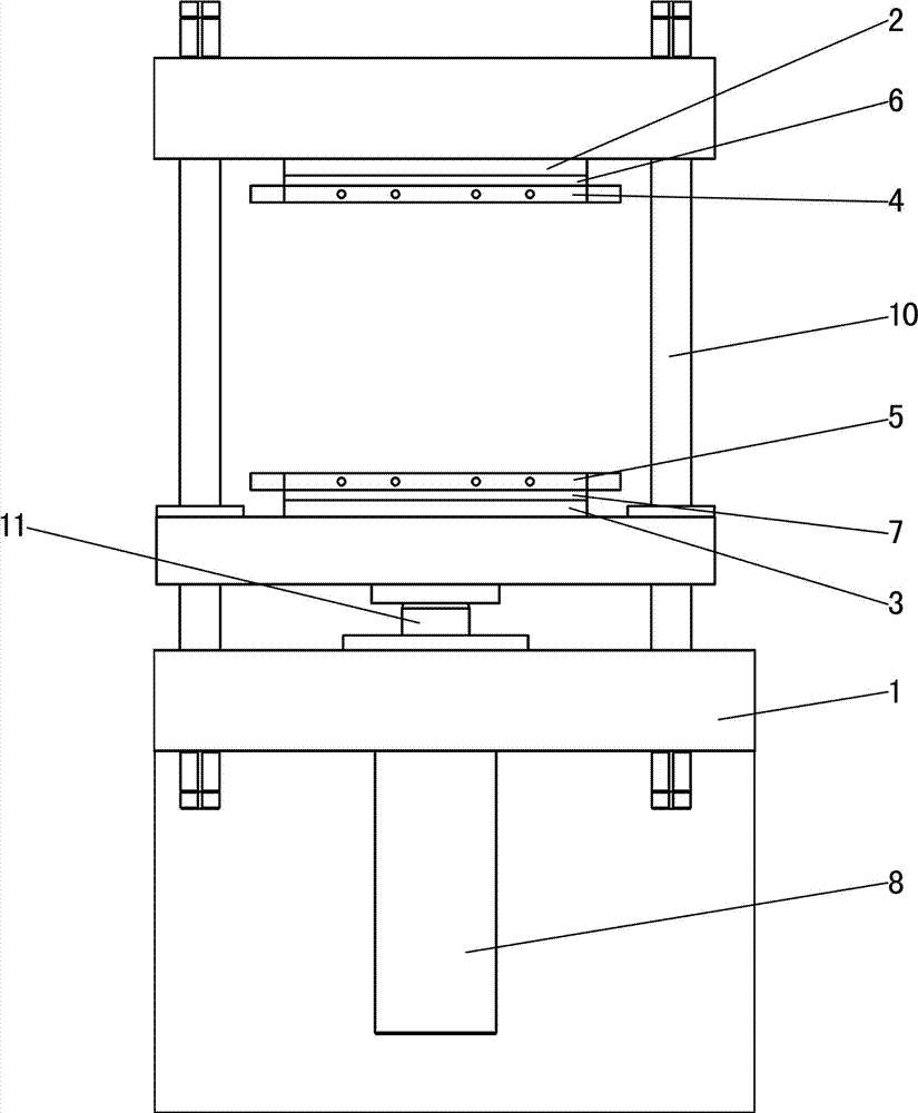
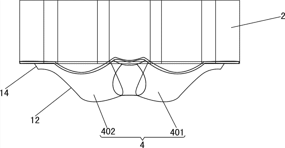
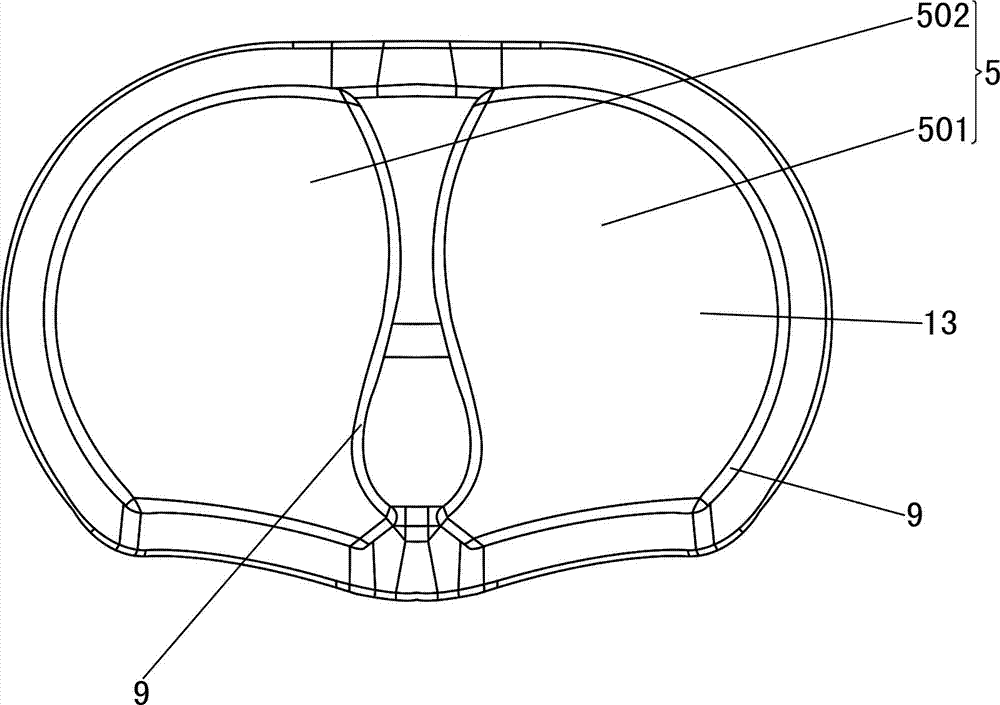
[0021] Such as figure 1 , figure 2 , image 3 and Figure 4 and Figure 5 As shown, this automatic breast cup thermoforming shearing machine includes a frame 1, an upper die table 2, a lower die table 3, an upper die 4, a lower die 5, an upper heating device 6, a lower heating device 7, a hydraulic pressure Cylinder 8 and circular cutter 9; upper die table 2 is fixedly installed on frame 1; lower die table 3 is installed on guide post 10 of frame 1 and can slide up and down along guide post 10; upper die 4 is installed on upper die The lower surface of the table 2; the lower mold 5 is installed on the upper surface of the lower mold table 3; the hydraulic cylinder 8 is installed on the frame 1, and the piston rod 11 of the hydraulic cylinder 8 is connected with the lower mold table 3; the upper mold 4 includes two upper molds ...


PUM


Abstract

The invention relates to a full-automatic hot press molding and shearing machine for a chest cup. The hot press molding and shearing machine comprises a rack, an upper mould table, a lower mould table, an upper mould, a lower mould, an upper heating device, a lower heating device, a hydraulic cylinder and an annular slicer, wherein the upper mould comprises at least one upper mould unit; the lower mould comprises at least one lower mould unit; the upper mould unit is provided with a first curved surface which protrudes outwards; the lower mould unit is provided with a second curved surface which depresses inwards; the annular slicer is positioned on the second curved surface and is arranged along the edge of the second curved surface; and a cutting edge of the annular slicer faces the first curved surface. Because the annular slicer is arranged along the edge of the second curved surface of the lower mould unit, the edge of the annular slicer faces the first curved surface, and the hydraulic cylinder is subjected to control on two steps of hot press molding and shearing, so that the full-automatic hot press molding and shearing of a chest cup are realized, the edge of the chest cup is smoother and more natural, the production efficiency is improved, the production cost is reduced, and accident work injuries are avoided.

Description

technical field [0001] The invention relates to a forming device, in particular to an automatic breast cup hot-press forming shearing machine for manufacturing breast cups by using sponge body. Background technique [0002] The breast cup is the sponge gasket in the bra. The two sides of the breast cup are two approximately spherical curved surfaces, and the edges of the curved surfaces are composed of four arcs that are connected end to end and are not on the same plane. [0003] At present, the production of breast cups generally adopts the breast cup forming machine with the following structure, including the frame, the upper mold table, the lower mold table, the upper mold, the lower mold, the upper heating device, the lower heating device and the cylinder; the upper mold table is fixedly installed on the frame The upper and lower mold tables are installed on the guide pillars of the frame and can slide up and down along the guide pillars; the upper mold is installed on ...

Claims


Application Information

Patent Timeline
Patent Type & Authority Applications(China)
IPC IPC(8): B29C51/32B29L31/48
Inventor 常建毅印松川
Owner 常建毅
Why Eureka
Try Eureka