Combined fluency strip

A fluent strip and combined technology, applied in the direction of conveyor objects, transportation and packaging, rollers, etc., can solve the problems of poor versatility, low material utilization rate, poor carrying capacity of fluent strips, etc., to achieve enhanced versatility, The effect of increasing the utilization rate and increasing the upper limit of the carrying capacity

Inactive Publication Date: 2012-12-12
WUXI JIESI LOGISTICS EQUIP
View PDF11 Cites 0 Cited by
  • Summary
  • Abstract
  • Description
  • Claims
  • Application Information

AI Technical Summary

Problems solved by technology

[0003] Aiming at the above-mentioned problems of poor load-bearing capacity, low material utilization rate, and low versatility of the existing fluent strips, the applicant conducted improvement research and provided a combined fluent strip, thereby improving the utilization rate of materials and increasing the load-carrying capacity of the fluent strips ability, while enhancing the versatility of the fluent bar with different functions, which is convenient for use and maintenance

Method used


Image

  • Combined fluency strip
  • Combined fluency strip
  • Combined fluency strip

Examples


Embodiment Construction

[0016] The specific implementation manner of the present invention will be described below in conjunction with the accompanying drawings.

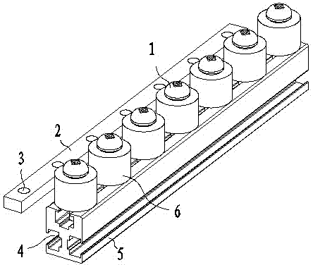
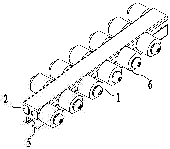
[0017] Such as figure 1 As shown, the present invention includes a metal bracket 5, a plug 2 and a roller 6; the side of the metal bracket 5 is provided with a T-shaped groove 4, the plug 2 is fixedly connected in the groove 4, and the plug 2 is provided with a facing groove The threaded holes 3 of the open end of 4, the threaded holes 3 are arranged at equal intervals, and are located on the same straight line; the roller 6 is connected in the threaded hole 3 by the bolt 1; in order to allow the roller 6 to rotate normally, the bolt 1 cannot be tightened.

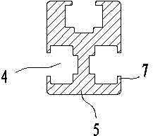
[0018] Such as figure 2 As shown, the two side walls and the top surface of the metal bracket 5 are respectively provided with T-shaped grooves 4, wherein the grooves on the two side walls are at the same height; the open end of the groove 4 has an inward flange 7, Thereby a stopper...


PUM


Abstract

The invention discloses a combined fluency strip. The combined fluency strip comprises a metallic support, a brake shoe and a roller, wherein the side surface of the metallic support is provided with a groove, the brake shoe is fixedly connected in the groove and provided with a threaded hole facing the open end of the groove, and the roller is connected in the threaded hole through a bolt. The combined fluency strip can improve the utilization rate of metallic materials, and enhance the bearing capacity of the fluency strip and the generality of fluency strips with different functions simultaneously, and is convenient in use and maintenance.

Description

technical field [0001] The invention relates to the field of logistics equipment, in particular to the field of fluent strips. Background technique [0002] Fluent strips are widely used in the assembly line of factories and the sorting area of ​​logistics distribution centers. At present, the fluent bar is generally composed of a U-shaped steel plate and a roller installed therein. The roller is connected between the two side walls of the U-shaped steel plate through the roller shaft, and the steel plate is generally formed by stamping and bending. Since the bending process has a certain limit on the thickness of the steel plate, the side walls of the fluent strips are relatively thin, which limits the bearing capacity of the fluent strips. In the fluent bar, the bottom surface of the U-shaped steel plate is not stressed, but due to the limitation of the manufacturing method, the bottom surface is also a steel plate material, which not only wastes material, but also increa...

Claims


Application Information

Patent Timeline
Patent Type & Authority Applications(China)
IPC IPC(8): B65G13/00B65G39/02
Inventor 王建兵
Owner WUXI JIESI LOGISTICS EQUIP
Why Eureka
Try Eureka