
Tension control and compensation mechanism of sample loom

A prototype loom and compensation mechanism technology, applied in small looms, looms, textiles, etc., can solve the problems of long trial production cycle, less number of warp weaving, no biaxial weaving, etc., to reduce equipment investment costs, avoid The shed is not clear and the effect of expanding the trial weaving range

Inactive Publication Date: 2012-12-12
NANTONG TEXTILE VOCATIONAL TECH COLLEGE
View PDF7 Cites 8 Cited by
  • Summary
  • Abstract
  • Description
  • Claims
  • Application Information

AI Technical Summary

Problems solved by technology

[0003] But there are still some defects: because the traditional sample loom can only control the warp of one system, when weaving patterned fabrics, the floating lengths of the ground warp and the flower warp are different, resulting in different weaving shrinkage rates of the flower warp and the ground warp. , the number of ground warp interlacing is large, the weaving shrinkage rate is large, the number of flower warp interlacing is small, and the weaving shrinkage
Ordinary sample looms do not have the function of biaxial weaving, so they cannot meet the requirements of sample cloth. If the sample is enlarged, it needs to be equipped with a large automatic loom for trial production. The trial production period is long and the cost is high.

Method used


Image

  • Tension control and compensation mechanism of sample loom
  • Tension control and compensation mechanism of sample loom
  • Tension control and compensation mechanism of sample loom

Examples


Embodiment Construction

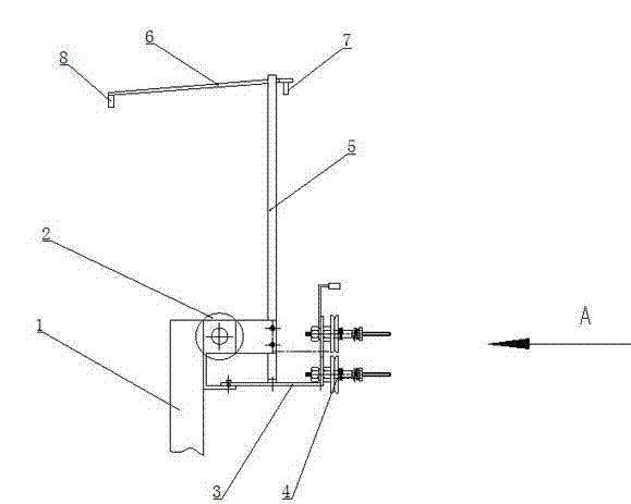
[0016] Such as figure 1 As shown, the let-off bracket 3 is installed on the frame 1 of the sample loom, and is close to the rear side of the back beam 2. On the let-off bracket 3, there are several warp let-off tensions evenly distributed along the horizontal direction with a certain pressure to clamp the warp yarns. Disk 4.

[0017] Such as figure 2 As shown, each warp let-off tension disc 4 is divided into upper and lower rows, and the warp let-off tension discs 3 in the upper and lower rows are staggered in the horizontal direction.

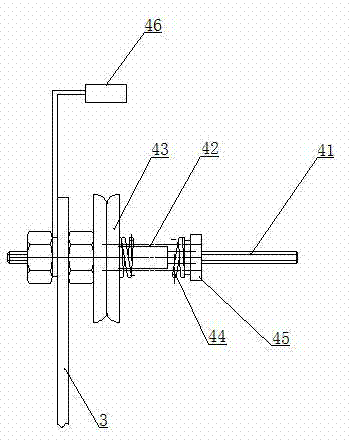
[0018] Such as image 3 , 4 As shown, the let-off tension disc 4 includes a mounting screw 41, a pressure plate mounting sleeve 42, a pressure plate 43, a compression spring 44 and a locking cap 45, and a pressure plate mounting sleeve 42 is installed in the middle of the mounting screw 31, and the pressure plate mounting sleeve 42 is set There is a guide slot opening along the axial direction of the mounting screw; the inner end of the m...


PUM


Abstract

The invention relates to a tension control and compensation mechanism of a sample loom. The tension control and compensation mechanism is characterized by comprising a let-off support, let-off tension disks and a tension compensation mechanism, wherein a plurality of let-off tension disks for clamping warp yarn at certain pressure are uniformly distributed on the let-off support along the horizontal direction, and the tension compensation mechanism is installed above the let-off support. When the warp yarn tension is higher, a strip-shaped elastic sheet is bent to reduce the warp yarn tension so that the warp yarn tension keeps consistent, so that cracked ends caused by ultra-high tension are avoided. When the warp yarn tension decreases, a strip-shaped tension compensating sheet resets and unbends to return to the original position, and the warp yarn is tensioned so as to avoid the unclear shed. The structure is utilized for being matched with an original warp yarn system of the sample loom to realize the independent and stable let-off control on two or more types of warp yarn, so that the sample loom can be used for test weaving of seersucker, spandex fabric and patterned fabric, the test weaving range of the sample loom is expanded, and the equipment investment cost is reduced.

Description

technical field [0001] The invention relates to a tension control mechanism for weaving, in particular to a tension control and compensation mechanism for a sample loom suitable for sample weaving of two or more warp yarn systems. Background technique [0002] The sample loom is the necessary equipment for professional teaching and training and textile product design technical work. With the continuous advancement of textile technology, especially in order to meet the market requirements of small batches, many patterns and fast cycles, the design and proofing work of textile enterprises is becoming more and more important, and the performance requirements of the textile industry for small sample looms are also gradually increasing. The current sample looms mainly include mechanical hedging dobby sample looms, electronic hedging sample looms and automatic rapier weft insertion sample looms. Among them, the electronic hedging sample loom is widely used by domestic yarn-dyed m...

Claims


Application Information

Patent Timeline
IPC IPC(8): D03D49/06D03D35/00
Inventor 陈栋瞿建新刘澎澎
Owner NANTONG TEXTILE VOCATIONAL TECH COLLEGE
Learn More