Aircraft engine cowl and process therefor

An aero-engine and fairing technology, applied in the field of fairing, can solve the problems of unfavorable inspection and maintenance of the weight core fairing, and achieve the effects of reducing the overall nacelle weight, reducing maintenance costs, and reducing the weight of the engine

Inactive Publication Date: 2012-12-12
MRA SYST
View PDF0 Cites 8 Cited by
  • Summary
  • Abstract
  • Description
  • Claims
  • Application Information

AI Technical Summary

Problems solved by technology

As operating temperatures have risen with newer engine designs, the increasingly harsh thermal environment of the engine's core cowling has necessitated thicker and heavier insulation 50, which trades off in weight (fuel economy), Clearance to surrounding components of the engine core 14 and inspection and maintenance of the core cowling 36 are disadvantageous

Method used


Image

  • Aircraft engine cowl and process therefor
  • Aircraft engine cowl and process therefor
  • Aircraft engine cowl and process therefor

Examples


Embodiment Construction

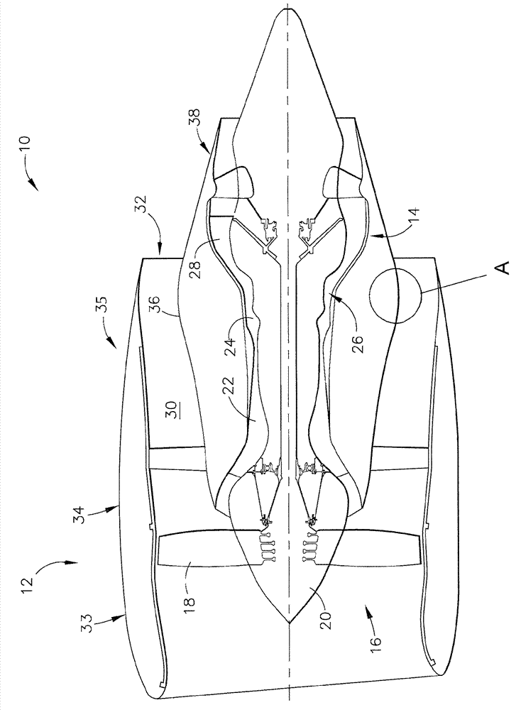
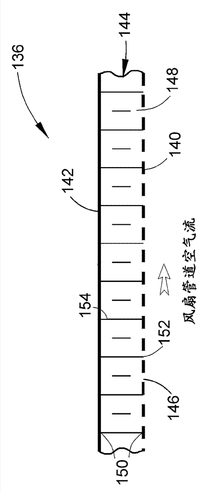
[0050] image 3 Shown are suitable for use in for example figure 1 A cross-section of a core cowling 136 used in a high-bypass gas turbine engine of the type shown in FIG. image 3 The fairing 136 shown in can be installed instead of figure 2 The core fairing 36, and is therefore particularly suitable for enclosing the core module 14 and defining figure 1 The inner boundary of the bypass duct 30 of the engine 10 is shown in .

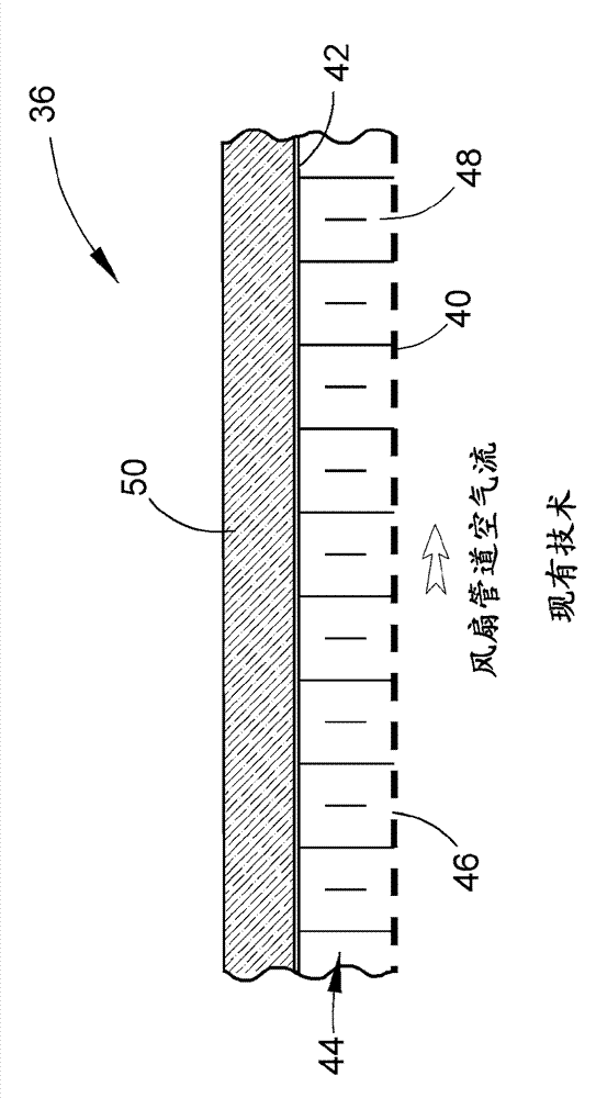
[0051] and figure 2 Similar to the prior art fairing 36, image 3 The fairing 136 shown in has a layered structure including skins 140 and 142 attached to a core component 144 . The cowling 136 is intended to be installed so that the skin 140 faces the air flow through the bypass duct 30 of the engine 10, and for this purpose the skin 140 is made as an acoustic skin 140 with a well-defined pattern determined by satisfying the specific acoustic Small and preferably equidistantly spaced perforations or holes 146 are formed. The holes 146 extend c...


PUM

PropertyMeasurementUnit
thicknessaaaaaaaaaa
thicknessaaaaaaaaaa

Abstract

A cowl (136) for an aircraft engine (10), and processes for producing the cowl (136) to have a layered construction and a high temperature capability. The layered construction of the cowl (136) includes a core member (144) having a cellular construction comprising internal hollow cells (148), and first and second skins (140,142) brazed to edges (152) of the cells (148) at opposite surfaces of the core member (144). The first and second skins (140,142) and the core member (144) are formed of titanium alloys, the first and second skins (140,142) are brazed to the core member (144), and the layered construction of the cowl (136) lacks a thermal insulation capable of thermally protecting the second skin (142) and brazed joints (150) that attach the second skin (142) to cell wall edges (152) at the second surface of the core member (144).

Description

technical field [0001] The invention generally relates to a cowling of the type used for aero-engines. More specifically, the present invention relates to a structure for a cowling suitable for use as a core cowling surrounding a core module of a high-bypass turbofan engine and functioning without the thermal protection of an insulating material. high temperature performance. Background technique [0002] figure 1 A high bypass turbofan engine 10 of a type known in the art is schematically shown. Engine 10 is shown schematically including a nacelle 12 and a core engine module 14 . A fan assembly 16 located forward of the core module 14 includes a spinner nose 20 projecting forward from the array of fan blades 18 . Both the rotating nose 20 and the fan blades 18 are supported by a fan disc (not shown). Core module 14 is shown including high pressure compressor 22 , combustor 24 , high pressure turbine 26 and low pressure turbine 28 . A substantial portion of the air ent...

Claims


Application Information

Patent Timeline
Patent Type & Authority Applications(China)
IPC IPC(8): F02C7/24
CPCB64D29/00Y10T29/4932
Inventor A.B.斯卡
Owner MRA SYST
Why Eureka
Try Eureka