Yawing and hub braking hydraulic system for wind driven generator set

A technology of wind turbines and brake hydraulics, which is applied in the control of wind turbines, wind turbines, wind power generation, etc. It can solve problems such as internal leakage of damage, shortening of system pressure holding time, seal damage, etc., and achieve the effect of eliminating system heat generation

Inactive Publication Date: 2012-12-12
杨洁
View PDF8 Cites 0 Cited by
  • Summary
  • Abstract
  • Description
  • Claims
  • Application Information

AI Technical Summary

Problems solved by technology

The direct consequences of this state are: first, the seals on the components inside the integrated block are aging——losing elasticity——destroyed—increased internal leakage; then the pressure holding time of the system is shortened—the motor oil pump starts frequently—— -The work of the motor oil pump is converted into heat energy to heat the hydraulic pump station; the viscosity of the oil decreases when the system is continuously heated and the motor oil pump is continuously started---the sealing performance of the system is further reduced; plus the integrated block and the solenoid valve and various external connections The different thermal expansion caused by the difference in the material of the joint will destroy the original seal and increase the leakage
The wind field maintenance personnel often have to replace it, seriously affecting the power generation efficiency of the wind field
[0004] In addition, the yaw mechanical positioning pin and hub brake must be in working condition when the fan needs to be overhauled, which will also make its control solenoid valve in the energized state for a long time, and this working condition will further lead to heating of the system

Method used


Image

  • Yawing and hub braking hydraulic system for wind driven generator set

Examples


Embodiment Construction

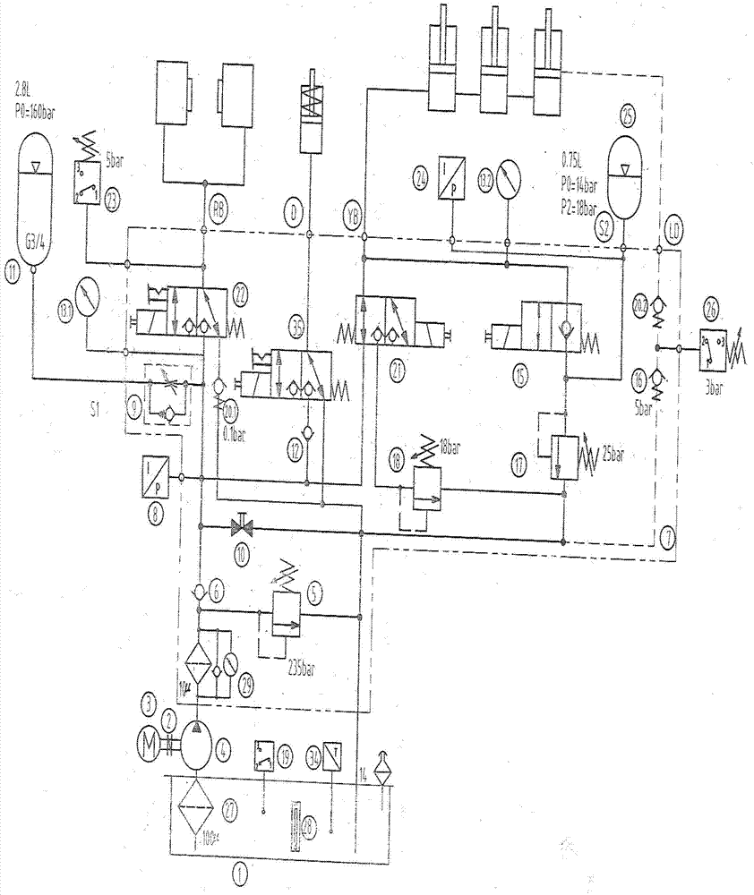
[0010] The specific embodiment of the present invention is: when the wind power generating set is in normal operation, all solenoid valves of the present invention are in the state shown in the figure, and their electromagnets are not electrified, and the hydraulic system will not be overheated due to the heating caused by the electromagnets being electrified. temperature; when the yaw is required, the main console issues an instruction, the No. 21 solenoid valve is energized and reversed, and the three yaw brake cylinders are connected to the oil return. They are damped by the 18bar back pressure established by the back pressure relief valve 18. Under the action, it is driven by the yaw drive mechanism to rotate smoothly and center the wind direction. In this process, as long as the pressure between the three brake cylinders and the overflow valve 18 is lower than the holding pressure in the accumulator 25, the pressure oil in the accumulator 25 will automatically open the zer...


PUM


Abstract

A yawing and hub braking hydraulic system for a wind driven generator set is composed of an oil tank 1, an oil pump 4, an oil filter 27, an oil filter 29, a pressure switch 8, a pressure switch 24, a one-way throttle valve 9, a solenoid valve 15, a solenoid valve 21, a solenoid valve 22, a solenoid valve 35, a power accumulator 11, a power accumulator 25, an overflow valve 5, an overflow valve 17, an overflow valve 18, a one-way valve 6, a one-way valve 12, a one-way valve 16, a one-way valve 20, a motor 3, a liquid level meter 28, a temperature control switch 19 and the like. The system is characterized in that functions of the two-position two-way solenoid valve 15 include zero-position unidirectional closing and energized-position inlet and outlet connection, the pressure switch 24 is connected on an oil path of the power accumulator 25, and the two-position three-way solenoid valve 22 which controls a hub brake and the two-position three-way solenoid valve 35 which controls a yawing mechanical positioning bolt are provided with manual mechanical positioning devices. By the aid of the system, heating during operation of the system can be effectively reduced, and the long-term normal operation of a main machine can be guaranteed.

Description

1. Technical field: [0001] The invention relates to a yaw and hub braking hydraulic system for a wind power generating set. This hydraulic control system device is especially suitable for variable-pitch wind turbines, and is also suitable for other types of wind turbines. 2. Background technology: [0002] In order to change the energy structure and use clean energy to serve mankind as soon as possible, wind power technology is developing rapidly. With the development of this technology, in order to improve the power generation efficiency of wind turbines, hydraulic transmission and control systems have been widely used in the control of blade yaw. [0003] In the existing impeller yaw control, it is mainly to ensure the stable braking of the nacelle when the wind turbine is working, and the damping force when the impeller yaw rotates against the positive wind direction to ensure the stable movement of the nacelle. In order to achieve this function, people use dual accumul...

Claims


Application Information

Patent Timeline
IPC IPC(8): F03D7/00
CPCY02E10/723Y02E10/72
Inventor 杨洁
Owner 杨洁
Why Eureka
Try Eureka