Far-field parameter calibration device and calibration method for antenna
A parameter calibration and antenna technology, which is applied in the antenna far-field parameter calibration device and the field of calibration, can solve the problems of poor test accuracy, large calibration errors, and low work efficiency, and achieve a large test frequency range, wide adaptability, and error elimination. Effect
- Summary
- Abstract
- Description
- Claims
- Application Information
AI Technical Summary
Problems solved by technology
Method used
Image

Examples
Embodiment 1
[0049] Calibration objects: 3 ETS 3115 antennas, numbered 6262#, 6663#, 6675#.
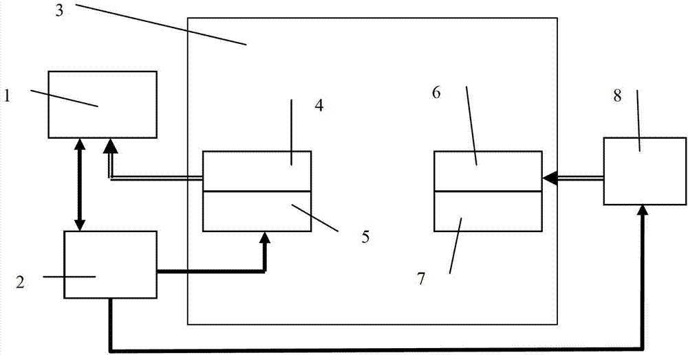
[0050] An antenna far-field parameter calibration device, comprising a receiver 1, a computer 2, a microwave anechoic chamber 3, a receiving antenna 4, a turntable 5, a transmitting antenna 6, a bracket 7 and a signal generator 8, the receiving antenna 4, the turntable 5, the transmitting The antenna 6 and the bracket 7 are placed in the microwave darkroom 3, the receiving antenna 4 is set on the turntable 5 and placed on the longitudinal axis of the darkroom space, the transmitting antenna 6 is set on the bracket 7 and placed on the longitudinal axis of the darkroom space, and the microwave darkroom 3 It is a cuboid, and the six sides of the microwave anechoic chamber 3 are paved with absorbing materials. The axial dimension of the microwave anechoic chamber 3 meets the far-field distance requirements of the receiving and transmitting antennas, and the cross-sectional size of the microwave anechoi...
Embodiment 2
[0091] Calibration object: 3 Xibao XB-WDB-0.4-3.5N antennas, number: 110321201#, 11032102#, 11032103#.
[0092] Calibration device: same as embodiment one
[0093] Using the above-mentioned antenna far-field parameter calibration device, the antenna far-field parameter is calibrated by the following method, and the steps include:
[0094] S1. Accurately locate the zero position
[0095] The horizontal center and vertical center of the receiving and transmitting antennas are respectively determined by a laser line throwing instrument. At the same time, the distance between the receiving and transmitting antennas is tested by a laser rangefinder to ensure that the mechanical zero position of the receiving and transmitting antennas is accurately positioned. The rolling axis of the turntable scans point by point to determine the electrical zero position of the antenna, and eliminate the error caused by the inconsistency between the mechanical zero position and the electrical zero...
PUM
 Abstract
Description
Claims
Application Information
 - R&D
- Intellectual Property
- Life Sciences
- Materials
- Tech Scout
- Unparalleled Data Quality
- Higher Quality Content
- 60% Fewer Hallucinations
Browse by: Latest US Patents, China's latest patents, Technical Efficacy Thesaurus, Application Domain, Technology Topic, Popular Technical Reports.
© 2025 PatSnap. All rights reserved.Legal|Privacy policy|Modern Slavery Act Transparency Statement|Sitemap|About US| Contact US: help@patsnap.com