System and method for detecting transponder cable

A detection system and transponder technology, applied in the direction of instruments, measuring electronics, measuring devices, etc., can solve problems such as train parking, affecting transportation efficiency, and failing to meet the longest application requirements, and achieve the effect of improving operating efficiency and reducing costs

Active Publication Date: 2015-05-06
BEIJING JIAODA SIGNAL TECH
View PDF5 Cites 0 Cited by
  • Summary
  • Abstract
  • Description
  • Claims
  • Application Information

AI Technical Summary

Problems solved by technology

[0003] When the LEU and the balise are connected normally, the LEU can transmit the necessary train operation information to the balise through the balise cable, and the balise sends the information to the balise transmission unit through electrical coupling, but when the LEU and the balise When an open circuit or short circuit fault occurs in the cable, the transponder cannot receive the message information of the LEU, and will send the default message information stored in itself, which generally causes the train to stop and affects the transportation efficiency. Therefore, the distance between the LEU and the transponder Real-time detection of cable status and instant alarm when the cable status is abnormal are very important
[0004] At present, the main method of transponder cable detection is to install a cable detection box on the LEU side, insert a current sensor into the transponder cable in series, and also incorporate a sensor into the cable. The cable detection box at the LEU end analyzes the current, voltage and Phase and impedance changes to detect the state of the transponder cable, but as the length of the transponder cable increases, the current, voltage, phase, impedance and attenuation of each point on the cable are not the same, when an open circuit or short circuit occurs at the end of the cable , this kind of change information is difficult to obviously feed back to the LEU end, so the accuracy of this detection method is generally only within 2500m, but in practical applications, the longest application of the cable between the LEU and the transponder has exceeded 3km, Therefore, in this case, using this method can no longer detect the status of the transponder cable. This detection method can no longer meet the needs of practical applications, and cannot meet the requirements of the longest application.

Method used


Image

  • System and method for detecting transponder cable
  • System and method for detecting transponder cable
  • System and method for detecting transponder cable

Examples


Embodiment 1

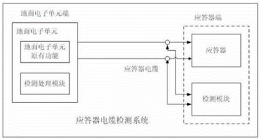
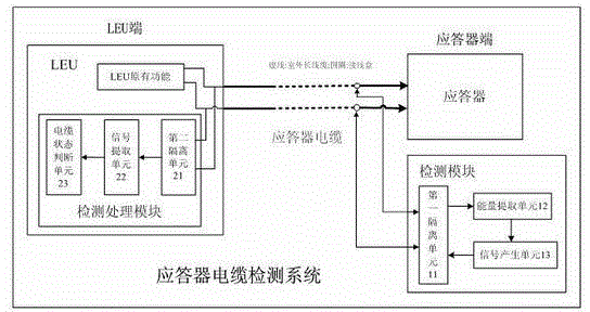
[0022] An embodiment of the present invention provides a transponder cable detection system, which is used to detect the state of the transponder cable between the ground electronic unit and the transponder, and is characterized in that the system includes: a detection module, located at the transponder The pigtail cable of the transponder cable is connected in parallel, and is used to obtain energy from the transponder cable, generate a cable detection signal and send it to the detection processing module through the transponder cable; Extracting the cable detection signal from the transponder cable, detecting the state of the transponder cable according to the cable detection signal, and providing the detection result to the subsequent equipment;

[0023] Wherein, the transponder cable between the ground electronic unit and the transponder mentioned in the present invention includes not only the connecting cable between the ground electronic unit and the transponder, but also...

Embodiment 2

[0038] The embodiment of the present invention provides a transponder cable detection method, which can accurately detect the state of the transponder cable over 3km, such as Figure 5 As shown, the detection method includes:

[0039] S1: extract the auxiliary energy signal from the transponder cable, and process the auxiliary energy signal;

[0040] S2: Generate a cable detection signal based on the auxiliary energy signal, and transmit the cable detection signal back to the transponder cable;

[0041] S3: extracting a cable detection signal from the transponder cable, and judging whether the transponder cable is normal according to the cable detection signal.

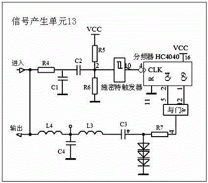
[0042] Wherein, in step S1 of the embodiment of the present invention, processing the auxiliary energy signal specifically refers to: performing DC conversion on the auxiliary energy signal, performing voltage stabilization processing, and further converting the above auxiliary energy signal into a power supply in th...


PUM


Abstract

The invention discloses a system and a method for detecting a transponder cable. The system is used for detecting the state of the cable between a lineside electronic unit and a transponder and comprises a detection module and a detection processing module, wherein the detection module is located at the transponder end and used for obtaining energy from the transponder cable to generate a cable detection signal and transmitting the cable detection signal to the detection processing module through the transponder cable; and the detection processing module is located at the lineside electronic unit end and used for extracting the cable detection signal from the transponder cable, detecting the state of the transponder cable according to the cable detection signal and providing detection results for a later-stage device. By means of the system and the method for detecting the transponder cable, the state of the transponder cable with the length smaller than 3km or larger than 3km can be accurately detected, the detection accuracy has nothing to do with the length of the transponder cable and can meet the longest application requirements, original performance of the transponder cable does not need changing, and the purpose of high-reliability detection on the state of the transponder cable can be achieved with low cost. Therefore, users can be timely conscious of abnormity of the transponder cable, and operation efficiency of trains is improved.

Description

technical field [0001] The invention relates to the field of railway communication signals, in particular to a detection system and a detection method for the status of a transponder cable between a ground electronic unit and a transponder. Background technique [0002] LEU (Lineside Electronic Unit, ground electronic unit) and transponders are indispensable ground signal equipment in the train operation control system. The transponders mentioned in the present invention specifically refer to active transponders, also known as variable information response Transponders, LEUs and transponders are connected by transponder cables to realize communication between indoor LEUs and transponders laid on outdoor rails. [0003] When the LEU and the balise are connected normally, the LEU can transmit the necessary train operation information to the balise through the balise cable, and the balise sends the information to the balise transmission unit through electrical coupling, but whe...

Claims


Application Information

Patent Timeline
Patent Type & Authority Patents(China)
IPC IPC(8): G01R31/02
Inventor 刘浩刘星宇
Owner BEIJING JIAODA SIGNAL TECH
Why Eureka
Try Eureka