
Inductive power source control device

A technology of inductive power supply and control device, applied in the direction of program control, computer control, general control system, etc., can solve the problems of waste of money, waste of electricity, holes and so on

Inactive Publication Date: 2012-12-12
邱金和
View PDF0 Cites 2 Cited by
  • Summary
  • Abstract
  • Description
  • Claims
  • Application Information

AI Technical Summary

Problems solved by technology

[0002] The first thing most people do when they get home from get off work is to turn on the light switch or TV switch. , Most of them will forget to turn off the power, which not only wastes electricity but also wastes money. If the power is not turned off, it will increase carbon emissions and force the earth's ozone layer to continue to break holes, which will cause global warming, which will not be liked by people. See you

Method used


Image

  • Inductive power source control device
  • Inductive power source control device
  • Inductive power source control device

Examples


Embodiment Construction

[0018] In order to achieve the above-mentioned purpose and effect, the technical means and structure adopted by the present invention, the features and functions of the preferred embodiments of the present invention will be described in detail as follows in order to facilitate a complete understanding.

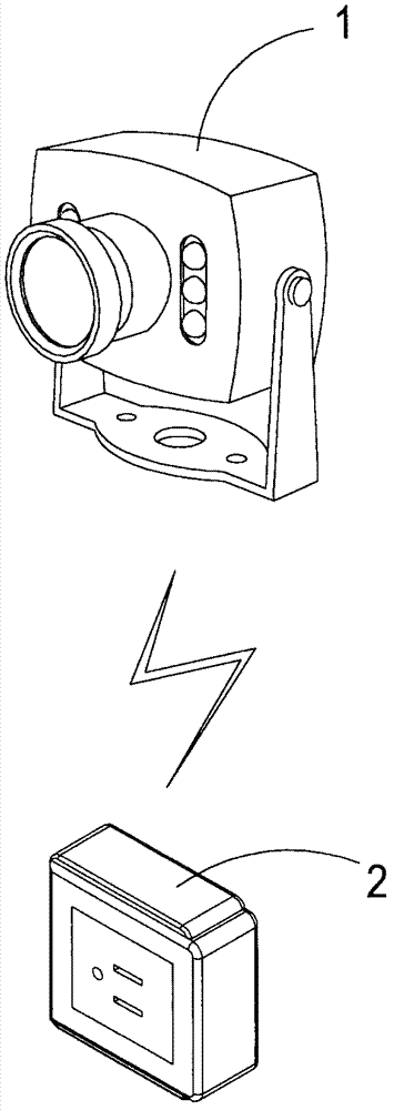
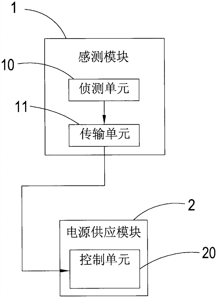
[0019] see figure 1 and figure 2 As shown, it is a perspective view and a schematic block diagram of a preferred embodiment of the present invention. It can be clearly seen from the figure that the inductive power supply control device of the present invention includes:

[0020] A sensing module 1 for detecting the position of an object, which is provided with a detection unit 10 and a transmission unit 11 communicatively connected with the detection unit 10, the detection unit 10 can be detected by thermal induction or infrared (Infrared, IR) the position of the object can be detected; and

[0021] A power supply module 2, which is provided with a control unit 20 capable o...


PUM


Abstract

The invention relates to an inductive power source control device. The device is mainly composed of a sensing module for sensing object positions and a power source supply module. The sensing module is applied in electrical equipment. When the sensing module senses that an object is approaching, the electrical equipment is guaranteed to move synchronously through the power source supply module connected with the sensing module in a wireless communication mode, so that electric power is saved and the sanitation problem that a plurality of people touch the electrical equipment is avoided.

Description

technical field [0001] The present invention provides a power control device, especially an inductive power control device capable of achieving both energy saving and sanitation and allowing connected electrical equipment to operate. Background technique [0002] The first thing most people do when they get home from get off work is to turn on the light switch or TV switch. , Most of them will forget to turn off the power, which not only wastes electricity but also wastes money. If the power is not turned off, it will increase carbon emissions and force the earth's ozone layer to continue to break holes, which will cause global warming, which will not be liked by people. See you. [0003] Therefore, how to solve the above-mentioned existing problems and shortcomings is the direction that the inventor of the present invention and related manufacturers engaged in this industry want to study and improve. Contents of the invention [0004] Therefore, in view of the above-menti...

Claims


Application Information

Patent Timeline
IPC IPC(8): G05B19/042G08C17/02
CPCY02B60/50
Inventor 邱金和
Owner 邱金和
Learn More