Touch screen panel

A touch screen and panel technology, applied in the direction of instruments, electrical digital data processing, data processing input/output process, etc., can solve the problems of increased resistance, poor durability, high cost of ITO layer preparation, etc., to achieve enhanced conductivity and improved durability performance, sensitivity and accuracy enhancement

Inactive Publication Date: 2012-12-12
TIANJIN FUNA YUANCHUANG TECH +1
View PDF6 Cites 8 Cited by
  • Summary
  • Abstract
  • Description
  • Claims
  • Application Information

AI Technical Summary

Problems solved by technology

However, as a transparent conductive layer, the ITO layer is usually prepared by ion beam sputtering or evaporation. During the preparation process, a high vacuum environment and heating to 200°C~300°C are required. Therefore, the preparation cost of the ITO layer higher
In addition, after the ITO layer is continuously bent, the resistance at the bend increases. As a transparent conductive layer, it has the disadvantages of insufficient mechanical and chemical durability, and there is a phenomenon of uneven resistance and a small range of resistance values.
As a result, existing touch screens have disadvantages such as poor durability, low sensitivity, and poor accuracy.

Method used


Image

  • Touch screen panel
  • Touch screen panel
  • Touch screen panel

Examples


Embodiment Construction

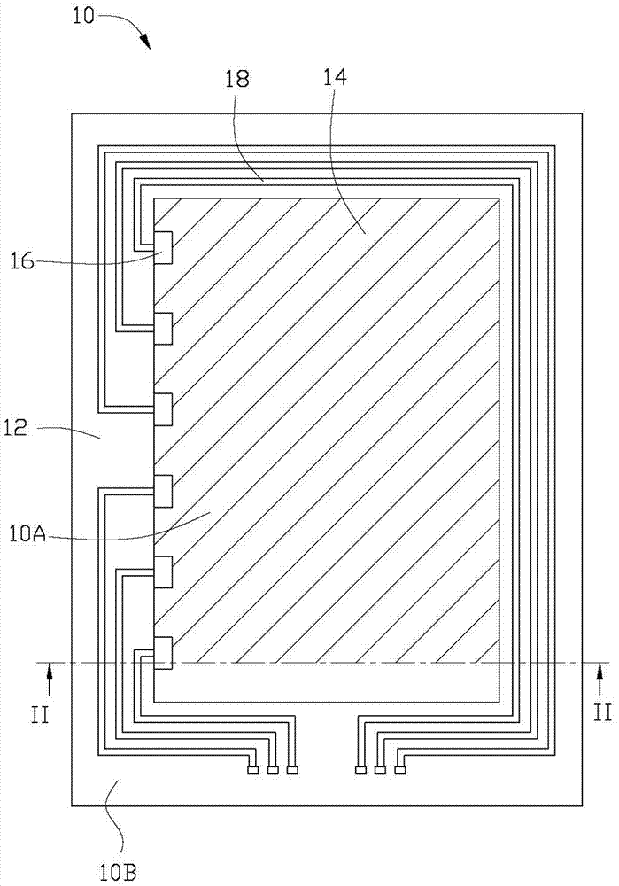
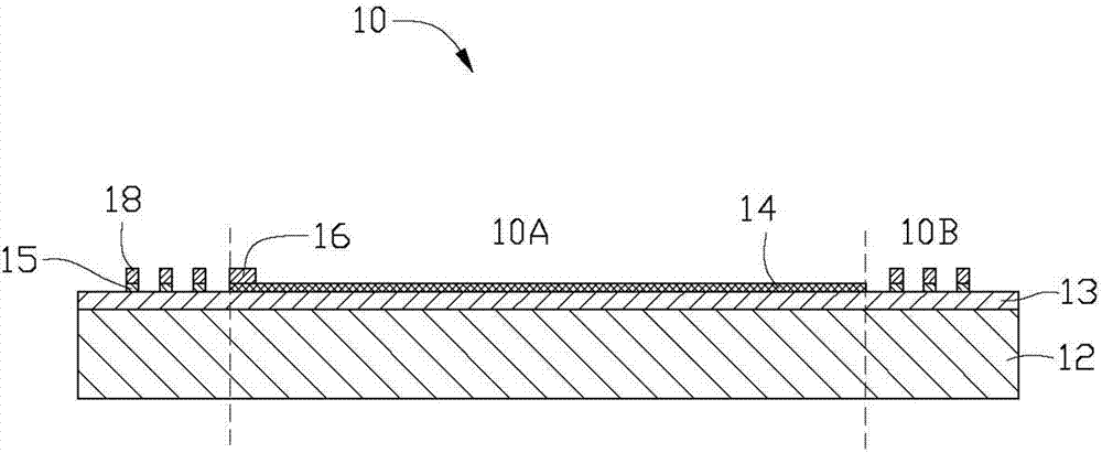
[0022] The touch screen panel provided by the present invention and the manufacturing method thereof will be further described in detail below with reference to the accompanying drawings and specific embodiments.

[0023] see figure 1 and figure 2 , the embodiment of the present invention provides a touch screen panel 10 , the touch screen panel 10 includes an insulating substrate 12 , an adhesive layer 13 , a transparent conductive layer 14 , at least one electrode 16 , and a conductive circuit 18 .

[0024] The touch screen panel 10 defines two areas: a touch area 10A and a wiring area 10B. The touch area 10A is an area where the touch screen panel 10 can be touched to realize a touch function, and the wiring area 10B is an area where the conductive lines 18 in the touch screen panel 10 are disposed. The wiring area 10B is a small area near the edge of the touch screen panel 10 , which may be located on at least one side of the touch area 10A. The touch area 10A is a rel...


PUM


Abstract

The invention relates to a touch screen panel. The touch screen panel is defined into two areas, namely a touch area and a routing area; the touch screen panel comprises an insulated base with a surface, an adhesive layer, a transparent conductive layer, at least one electrode, and a conductive circuit, wherein the adhesive layer is arranged on the surface of the insulated base; the transparent conductive layer comprises a carbon nano tube layer and is fixed on the surface of the insulated base through the adhesive layer; at least one electrode is electrically connected with the transparent conductive layer; the conductive circuit is electrically connected with the at least one electrode; the transparent conductive layer is just arranged on the touch area; the conductive circuit is just arranged on the surface of the adhesive layer in the routing area, and the touch screen panel further comprises a carbon nano tube wire arranged between the conductive circuit and the adhesive layer.

Description

technical field [0001] The invention relates to a touch screen panel, in particular to a touch screen panel based on carbon nanotubes. Background technique [0002] In recent years, along with the high performance and diversification of various electronic devices such as mobile phones and touch navigation systems, the number of electronic devices in which a light-transmitting touch panel is mounted on the front of a display device such as a liquid crystal is increasing. A user of such an electronic device performs operations by pressing the touch panel with a finger, a stylus, or the like while visually confirming display contents of a display device located behind the touch panel through the touch panel. Thereby, various functions of the electronic device can be operated. [0003] According to different working principles and transmission media of touch screens, existing touch screens are divided into four types, namely resistive type, capacitive type, infrared type and su...

Claims


Application Information

Patent Timeline
Patent Type & Authority Applications(China)
IPC IPC(8): G06F3/041
Inventor 郑嘉雄洪宏毅吴志笙
Owner TIANJIN FUNA YUANCHUANG TECH
Why Eureka
Try Eureka