Built-in air bag type anti-collision device

A technology of anti-collision devices and airbags, applied in road safety devices, roads, roads, etc., can solve the problems of short service life, high investment cost of anti-collision facilities, poor anti-collision effect, etc., and achieve convenient construction, simple construction steps, good effect

Inactive Publication Date: 2012-12-19
CHANGAN UNIV
View PDF5 Cites 5 Cited by
  • Summary
  • Abstract
  • Description
  • Claims
  • Application Information

AI Technical Summary

Problems solved by technology

[0003] The technical problem to be solved by the present invention is to provide a built-in airbag type anti-collision device for the above-mentioned deficiencies in the prior art. The existing anti-collision facilities for vehicles have defects and deficiencies such as high input cost, short service life, and poor anti-collision effect

Method used


Image

  • Built-in air bag type anti-collision device
  • Built-in air bag type anti-collision device

Examples


Embodiment 1

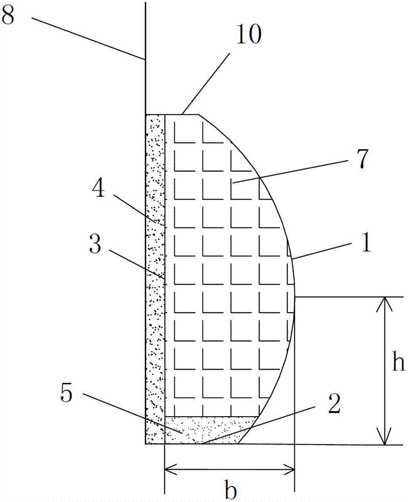
[0036] Such as figure 1 A built-in airbag-type anti-collision device shown includes an outer steel wall panel 1 and an inner steel wall panel 3 located inside the outer steel wall panel 1 , and a gap between the outer steel wall panel 1 and the inner steel wall panel 3 An anti-collision cavity is formed, the bottom of the anti-collision cavity is provided with a layer of counterweight cushion 5, and the anti-collision cavity on the top of the counterweight cushion 5 is densely filled with a plurality of rubber airbags 7, and the plurality of The rubber airbags 7 are arranged on the same plane. The lined steel wall plate 3 is located outside the device to be protected, and an energy-absorbing cushion 4 is arranged between the lined steel wall plate 3 and the device to be protected. The outer steel wall plate 1 and the inner steel wall plate 3 are arranged on the same plane, and the vertical heights of the two are the same. The outer steel wall plate 1 is an outwardly protrudin...

Embodiment 2

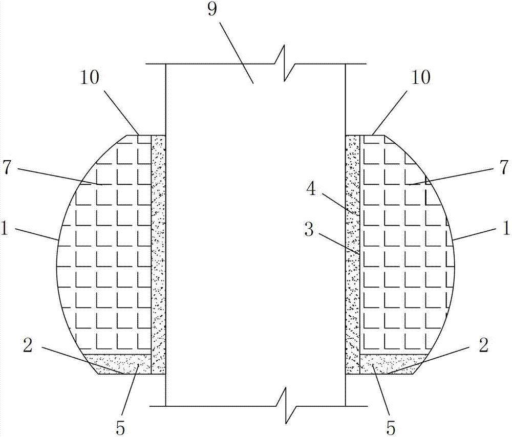
[0061] In this example, if figure 2 As shown, the difference from Example 1 is that: the protection device to be protected is an anti-collision column 9; the lined steel wall plate 3 arranged on the outside of the anti-collision column 9 is an annular steel plate 1 bent from a straight steel plate 2, The outer steel wall plate 1 located on the outer side of the first ring-shaped steel plate is the second ring-shaped steel plate bent by the second circular-arc-shaped steel plate. The cross-section of the second circular-arc-shaped steel plate is arc-shaped; The outer side of the anti-collision column 9, and the second ring-shaped steel plate is set on the outer side of the first ring-shaped steel plate; the plurality of rubber airbags arranged in the anti-collision cavity between the first ring-shaped steel plate and the second ring-shaped steel plate 7. Lay out along the circumferential direction. Between the first ring-shaped steel plate and the second ring-shaped steel pla...


PUM


Abstract

The invention discloses a built-in air bag type anti-collision device which comprises an outer steel wall plate and a lining steel wall plate, wherein an anti-collision cavity is formed between the outer steel wall plate and the lining steel wall plate; a counter weight pad layer is arranged at the bottom of the anti-collision cavity; multiple rubber air bags on the same plane are densely filled in the anti-collision cavity at the upper part of the counter weight pad layer; the lining steel wall plate is located on the outer side of a device needing protection; an energy absorption pad layer is arranged between the lining steel wall plate and the device needing protection; the outer steel wall plate and the lining steel wall plate are arranged on the same plane and have the same vertical height; the outer steel wall plate is an outward-protruding arc anti-collision plate; the devices needing protection are arranged on the two sides of a channel or road; and each device needing protection is an anti-collision guardrail, anti-collision wall or anti-collision column. The device disclosed by the invention has the advantages of reasonable structure design, low investment cost, long service life and good using effect, is convenient to construct, and can overcome the shortcomings of higher investment cost, shorter service life, poor anti-collision effect and the like of the anti-collision facility of the existing traffic tool.

Description

technical field [0001] The invention relates to an anti-collision device, in particular to a built-in airbag type anti-collision device. Background technique [0002] Nowadays, in the process of construction of transportation facilities, the requirements for traffic safety facilities are becoming more and more stringent, and they are more widely used in daily life, with various types and styles. Among them, anti-collision facilities for vehicles, ships and other vehicles are extremely important safety protection facilities among many types of traffic safety facilities. However, most of the anti-collision facilities used for vehicles can only withstand a single impact, so frequent repairs or replacements are required, which is time-consuming and labor-intensive, and the input cost is high; and if the repairs or replacements are not timely, traffic The safety protection effect is out of the question. In addition, the existing anti-collision facilities can offset the limited ...

Claims


Application Information

Patent Timeline
Patent Type & Authority Applications(China)
IPC IPC(8): E01F15/00
Inventor 刘永健徐兵徐芳尹冠生荀勇
Owner CHANGAN UNIV
Why Eureka
Try Eureka