
Gas-stove, gas-stove panel, and pot racks

A gas stove and panel technology, which is applied in the field of kitchen utensils, can solve the problems of insufficient air volume in the Venturi mixing tube, deviation of the pot frame from the burner, and insufficient combustion of gas, etc.

Active Publication Date: 2012-12-19
BSH ELECTRICAL APPLIANCES JIANGSU
View PDF6 Cites 6 Cited by
  • Summary
  • Abstract
  • Description
  • Claims
  • Application Information

AI Technical Summary

Problems solved by technology

[0005] The problem to be solved by the present invention is that the gas cooker of the prior art easily leads to insufficient air volume entering the Venturi mixing tube so that the combustion of gas is not sufficient; device

Method used


Image

  • Gas-stove, gas-stove panel, and pot racks
  • Gas-stove, gas-stove panel, and pot racks
  • Gas-stove, gas-stove panel, and pot racks

Examples


no. 1 Embodiment

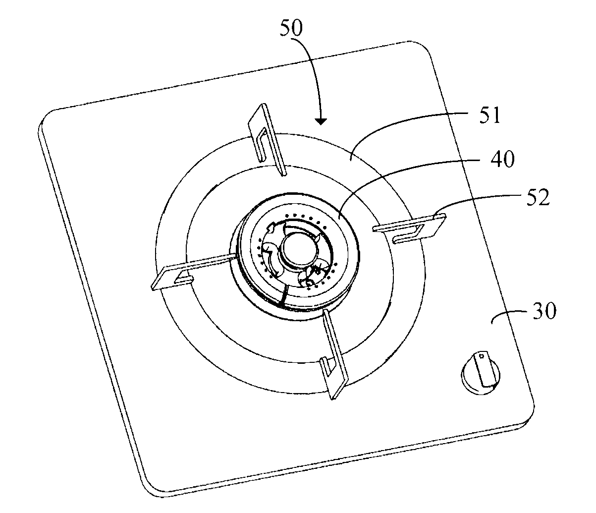
[0052] refer to image 3 , the gas cooker of the present invention includes: a panel 30, a burner 40, a Venturi mixing tube (not shown) and a pan support 50; the Venturi mixing tube communicates with the burner 40 for mixing The gas after the air is supplied to the burner 40; the pot support 50 includes a support frame 51 and a support member 52, the support member 52 is arranged on the support frame 51, and the pot (not shown) is placed on the support member 52, the support 52 is used to support the pot. Figure 4 is a perspective view of the panel of the first specific embodiment of the present invention, Figure 5 It is a top view of the panel of the first specific embodiment of the present invention, Figure 6 for Figure 5 The schematic diagram of the cross-sectional structure of the panel along the A-A direction, combined with reference Figure 4 , Figure 5 , Figure 6 , the panel 30 has a boss 31 adapted to the shape of the support frame 51, and the boss 31 has a...

no. 2 Embodiment

[0066] Compared with the first specific embodiment, in the second specific embodiment, the outer ring blocking part is in contact with the panel to play the role of supporting the pan support, and there is a through hole on the outer ring blocking part, and the outer ring blocking part has a Through holes, outside air flows into the Venturi mixer through the through holes, the gaps, and the through holes of the boss in sequence on the outer ring blocking portion.

[0067] The structures of other components are the same as those in the first specific embodiment, and will not be repeated here.

no. 3 Embodiment

[0069] In the third specific embodiment, the support frame is ring-shaped, including a ring-shaped body and an outer ring stopper and an inner ring stopper provided on the body; the outer ring stopper is located outside the boss, and the shield boss The outer side of the platform, the bottom end of which is in contact with the panel to support the pot support, and the outer ring blocking part has a through hole, and the outside air passes through the through hole, the gap, and the through hole of the boss in turn on the outer ring blocking part Then flow into the Venturi mixing tube; the inner ring blocking part is located on the inside of the boss, and there is a gap between the bottom end of the inner ring blocking part and the panel, and the inner ring blocking part and the boss Medial contact. Since the inner ring blocking part is in contact with the inner side of the boss, the air in the gap can also be confined in the space of the gap, and will not flow out through the i...


PUM


Abstract

The invention relates to a gas-stove, a gas-stove panel, and pot racks. The gas-stove comprises a panel (30), combustors (40), Venturi mixing tubes, and pot racks (50). The Venturi mixing tubes communicate with the combustors (40), and are used for providing a mixture of air and fuel gas to the combustors (40). The pot racks (50) comprise supporting racks (51) and supports (52). The supports (52) are arranged on the supporting racks (51), and are used for supporting pots. Bosses (31) with shapes matching those of the supporting racks (51) are arranged on the panel. Each boss comprises at least one through hole (32). The supporting racks (51) are positioned above the bosses (31). Spaces (60) are formed between the bosses (31) and the supporting racks (51). The spaces (60) communicate with the outside. Outside air sequentially passes through the spaces (60) and the through holes (32), and flows into the Venturi mixing tubes. The outside air can also enter the Venturi mixing tubes through the spaces and the holes on the bosses, such that a problem of insufficient fuel gas combustion caused by insufficient air in cupboards can be solved.

Description

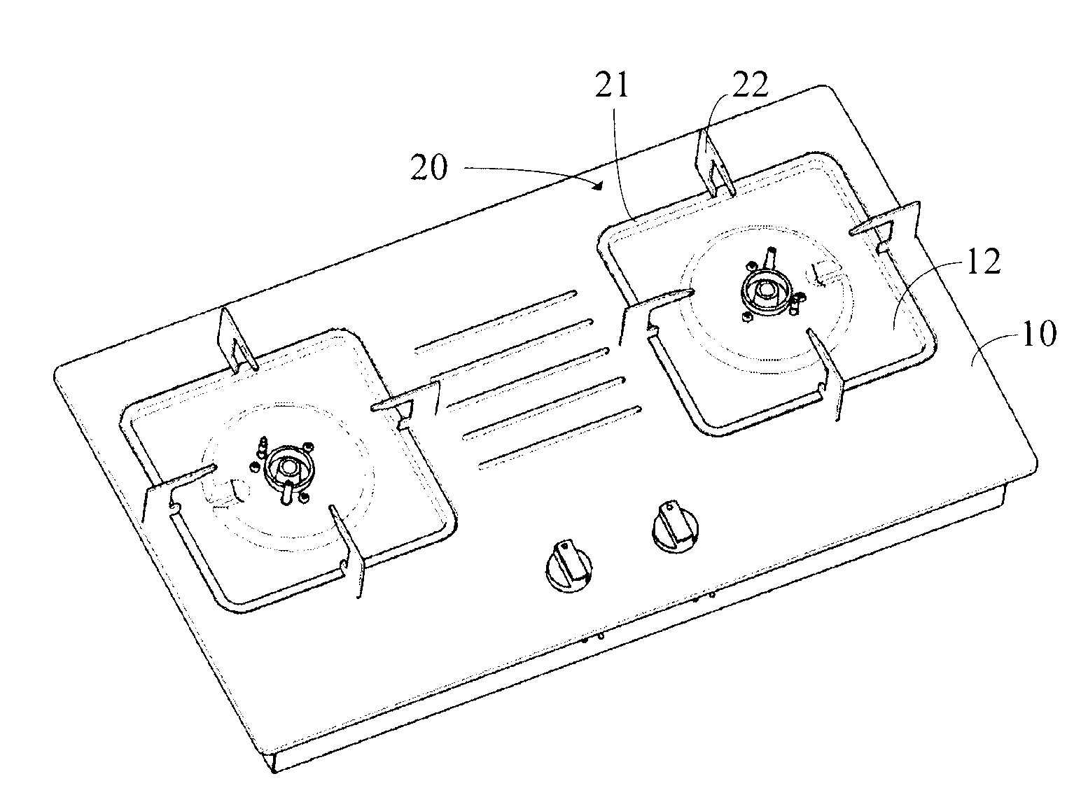
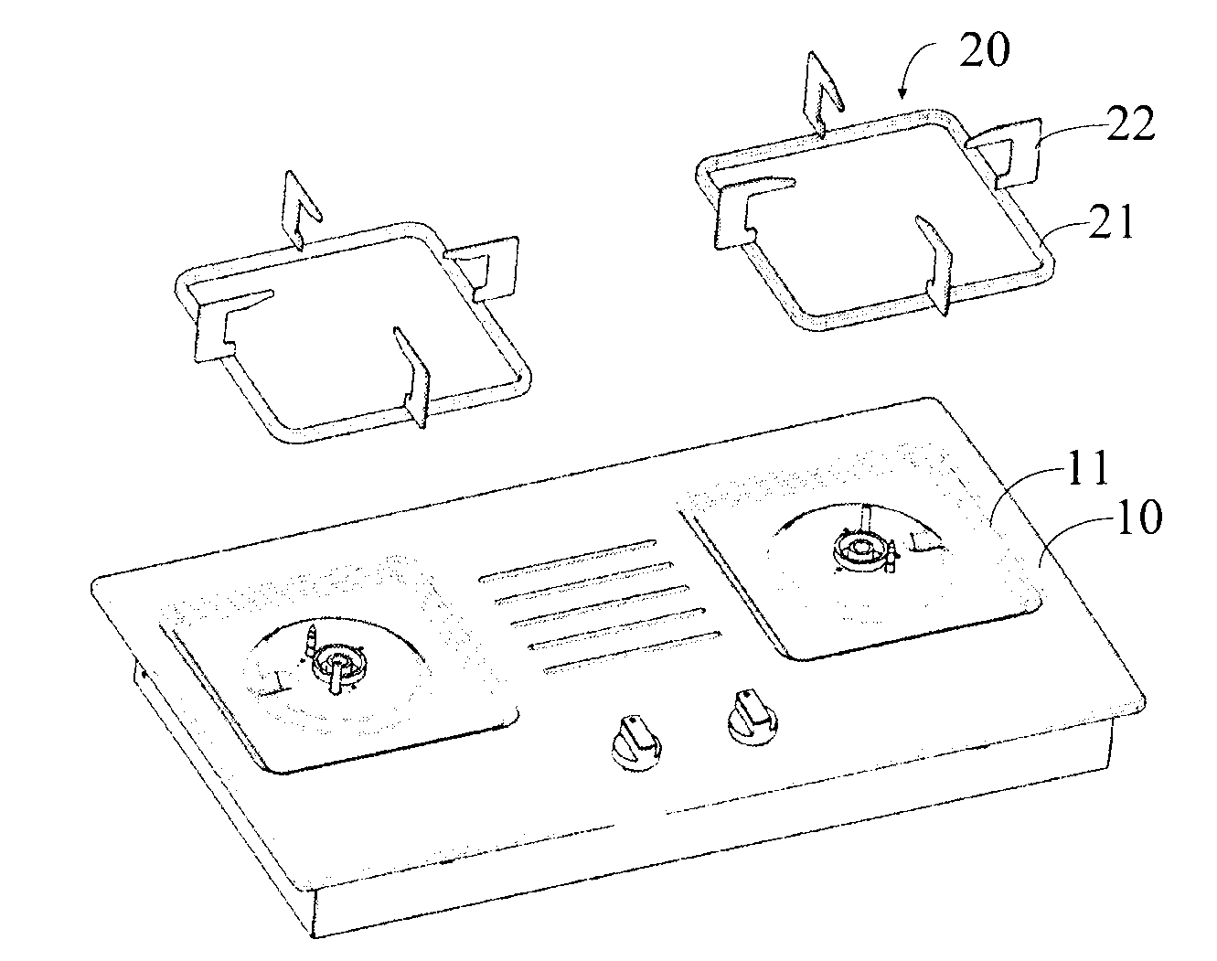
technical field [0001] The invention relates to the field of kitchen utensils, in particular to a gas cooker, a panel of the gas cooker and a pot support. Background technique [0002] figure 1 It is a three-dimensional view of an embedded gas stove in the prior art, figure 2 for figure 1 For the three-dimensional exploded view of the gas stove shown, refer to figure 1 and figure 2 , the gas cooker mainly includes a panel 10, a pot support 20, a burner (not shown in the figure), a Venturi mixing tube (not shown in the figure), a nozzle (not shown in the figure), a damper (not shown in the figure) and a damper adjustment device (not shown in the figure). The panel 10 forms a space with the bottom plate and the side wall of the gas stove, and the Venturi mixing tube, the nozzle, the damper and the damper adjusting device are located in the space. The Venturi mixing tube is an important part of the gas cooker. The gas enters the Venturi mixing tube through the nozzle, a...

Claims


Application Information

Patent Timeline
Patent Type & Authority Applications(China)
IPC IPC(8): F24C3/00F24C3/08F24C15/10
Inventor 威尔曼・卡尔斯顿郭丽杨萌苏卡姆・罗文
Owner BSH ELECTRICAL APPLIANCES JIANGSU
Learn More