Roller rotating and driving slag removal hearth

A technology of drum rotation and slag discharge furnace, which is applied in the direction of non-flammable liquid/gas transportation, combustion method, solid fuel combustion, etc. It can solve the problems of difficult discharge of coke-like slag, too large furnace, insufficient combustion, etc., to achieve Facilitate local repair and maintenance, improve combustion efficiency, and save labor costs

Pending Publication Date: 2018-11-23
正圆合(长春)生物质科技有限公司
View PDF5 Cites 2 Cited by
  • Summary
  • Abstract
  • Description
  • Claims
  • Application Information

AI Technical Summary

Problems solved by technology

[0003] In order to overcome the shortcomings of existing large and medium-sized biomass boilers using chain grates or reciprocating grates, and small biomass boilers using nest firing, the invention provides a drum rotary drive slagging furnace, which solves the problem of chain grates and reciprocating grates. Large grate size, large combustion furnace, poor primary and secondary air distribution, resulting in insufficient combustion, high operating costs, high boiler manufacturing costs, high market sales prices, and low competitiveness
[0004] The beneficial effect of the patent of the present invention is that it replaces the chain grate and reciprocating grate of large and medium-sized biomass boilers, and is applied to small biomass boilers, which solves the problem of difficult discharge of charred slag generated during the combustion of biomass boilers. It also solves the problem that the furnace is too large and the combustion of biomass fuel is insufficient. At the same time, it meets the technical requirements of the primary and secondary air distribution of the biomass boiler, improves the combustion efficiency of the biomass boiler, and reduces the operating cost of the biomass boiler. Furnace realizes fully automatic slagging, saving labor costs

Method used


Image

  • Roller rotating and driving slag removal hearth
  • Roller rotating and driving slag removal hearth
  • Roller rotating and driving slag removal hearth

Examples


Embodiment Construction

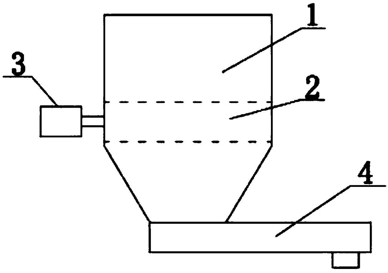
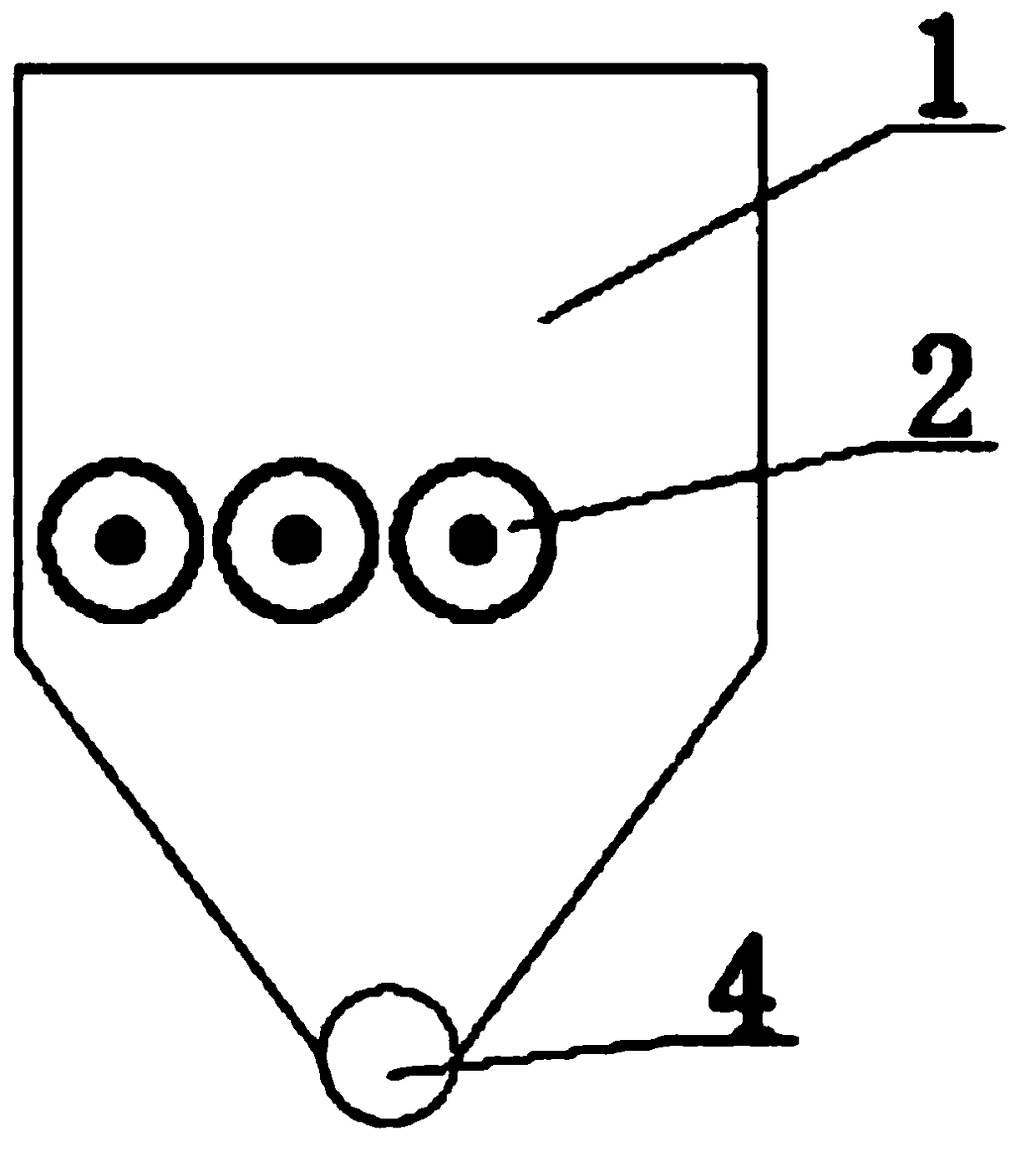
[0009] exist figure 1 Among them, there are 3 drums (2) at the bottom of the furnace square box (1), and the 3 drums are driven by the motor (3) to rotate in the same direction to drive the granular fuel and the slag produced by the combustion forward, and the burnt slag Roll down to the slag remover (4) at the bottom of the furnace, and then be automatically transported to the outside of the boiler.

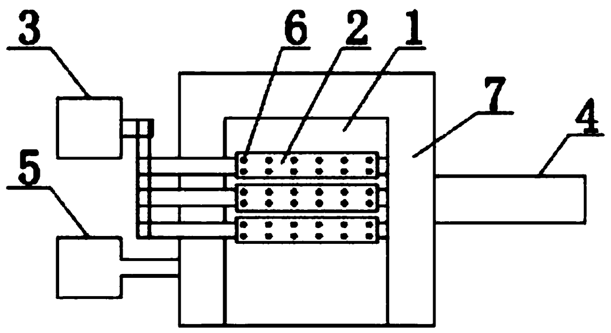
[0010] exist figure 2 In the example shown, the three drums (2) are installed in parallel at the bottom of the furnace and rotate in the same direction driven by the motor (3). The drums (2) are provided with air ducts (6), which enter the bottom of the drums through the fan (5). In the bellows, the wind in the bellows at the bottom of the drum passes through the air channel (6) on the drum to distribute air to the fuel on the drum at one time, and the three sides of the furnace are equipped with air channel boxes (7) to face the drum (2) from the left, right and rear The fue...


PUM


Abstract

The invention relates to a roller rotating and driving slag removal hearth, which can be used for fully automatically discharging slag generated when a biomass boiler burns out of the boiler. According to the roller rotating and driving slag removal hearth, one or multiple circular rollers are arranged in a square box body of the hearth, and the circular rollers are driven to rotate by a motor, sothat slag generated when biomass fuel burns can be automatically discharged out of the hearth and then can be discharged out of the boiler by virtue of an automatic slag extractor at the bottom of the hearth, and the full-automatic discharge of the slag is realized. Air channels are formed in three directions including the left side, the right side and the back side of the square box body of thehearth so as to perform secondary air distribution on the fuel in the hearth, air channel holes are formed in the rotary rollers, bellows are arranged on the lower ends of the air channel holes, air in the bellows is upward so as to perform primary air distribution on the biomass fuel during burning, and additionally, residual ash in the air channel holes in the rollers can be blown off.

Description

technical field [0001] The patent of the present invention relates to an automatic slagging furnace device for supporting boilers, especially for biomass boilers. Background technique [0002] At present, in order to solve the coking problem of biomass boilers when burning biomass particles, most of the biomass boiler manufacturers on the market use chain grates or reciprocating grates for coal-fired boilers, chain grates and reciprocating grates. The disadvantages are that the air distribution is not good at one time, the biomass fuel is not burned completely, and the loss is large. In addition, the grate is large in size, high in cost, high in failure rate, and inconvenient to maintain. They can only be used for large and medium-sized biomass boilers, small boilers It cannot be applied, because it is a technology diverted from coal-fired boilers, it cannot fully meet the technical requirements of biomass boilers. Although the chain grate and reciprocating grate solve the ...

Claims


Application Information

Patent Timeline
IPC IPC(8): F23B30/10F23J1/06F23L9/00
CPCF23B30/10F23J1/06F23L9/00
Inventor 栾禄春
Owner 正圆合(长春)生物质科技有限公司
Why Eureka
Try Eureka