Fault detection system, fault detection method and module

A technology of fault detection and blockage detection, which is applied in the direction of measuring devices, measuring heat, testing of machine/structural components, etc., and can solve problems such as blockage and faults

Inactive Publication Date: 2012-12-19
SANY HEAVY MACHINERY
View PDF5 Cites 21 Cited by
  • Summary
  • Abstract
  • Description
  • Claims
  • Application Information

AI Technical Summary

Problems solved by technology

[0005] In view of this, the present invention aims to propose a fault detection method and fault detection system to solve the problem of faults caused by blockage of construction machinery such as air-conditioning condensers, air-conditioning evaporators or oil radiators, water radiators, etc.

Method used


Image

  • Fault detection system, fault detection method and module
  • Fault detection system, fault detection method and module
  • Fault detection system, fault detection method and module

Examples


no. 1 example

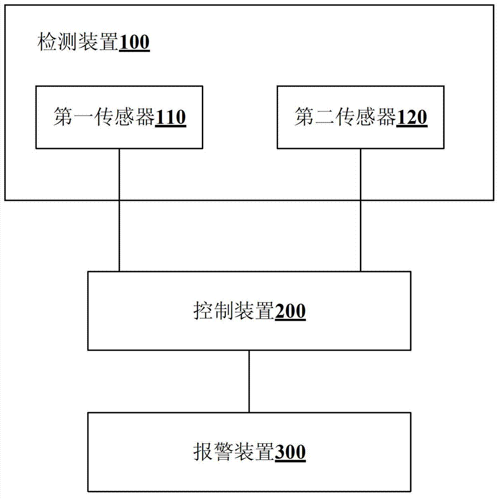
[0024] refer to figure 1 . The fault detection system of this embodiment is used for the blockage detection of temperature adjustment equipment, and includes a detection device 100 , a control device 200 and an alarm device 300 .

[0025] Wherein, the detecting device 100 includes a first temperature sensor 110 disposed at the inlet of the temperature regulating device and a second temperature sensor 120 disposed at the outlet of the temperature regulating device. The control device 200 is connected to the first temperature sensor 110 and the second temperature sensor 120, and is used to send a first alarm driving signal when the temperature difference between the inlet and outlet of the temperature adjustment device is lower than the minimum value of the predetermined normal temperature drop; or, It is used to issue an alarm and a second alarm driving signal when the inlet temperature of the temperature adjustment equipment is higher than the maximum value of the predetermin...

no. 2 example

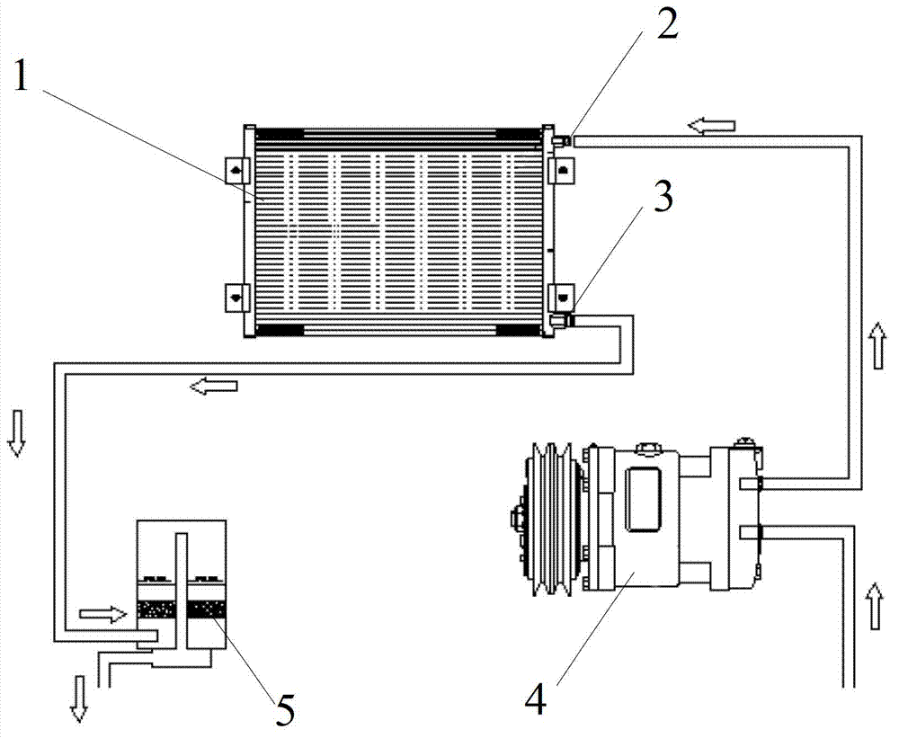
[0028] refer to figure 2 with image 3 .

[0029] In this embodiment, an air conditioner condenser is taken as an example to describe the specific application of the fault detection system in detail.

[0030] In this system, temperature sensor 2 and temperature sensor 3 need to be installed at the outlet and inlet of condenser 1 respectively. The installation positions are as follows: figure 2 shown. In the air conditioning system, the inlet temperature of condenser 1 is about 80°C, and the outlet temperature of the condenser is about 60°C or less. The temperature difference between the two inlets and outlets is relatively large, so it is more accurate to judge the clogging degree of the condenser according to whether the temperature difference is normal or not. In addition, a drying bottle 5 is also connected to the outlet of the condenser.

[0031] The inlet of the condenser 1 is connected to the compressor 4, which is the highest temperature point during the cooling ...


PUM


Abstract

The invention discloses a fault detection system, a fault detection method and a module. The fault detection system comprises a detection device, a control device and an alarm device. The detection device comprises a first temperature sensor and a second temperature sensor which are arranged at the inlet and the outlet of a temperature regulating apparatus. The control device is connected with the first temperature sensor and the second temperature sensor, and used for sending a first alarm driving signal when the temperature difference between the inlet and the outlet of the temperature regulating apparatus is lower than the minimum value of a predetermined normal temperature drop, or sending a second alarm driving signal when the temperature of the inlet of the temperature regulating apparatus is higher than the maximum value of a predetermined inlet temperature; and the alarm device is connected with the control device, and used for giving an alarm on a fault under the action of the first alarm driving signal or the second alarm driving signal. The fault detection system well solves the fault problems caused by blockage of engineering machines such as an air-conditioning condenser and an air-conditioning evaporator, an oil radiator and a water radiator.

Description

technical field [0001] The invention relates to the field of construction machinery, in particular to a fault detection system, a fault detection method and a module of an air conditioning system or a heat dissipation system in the construction machinery. Background technique [0002] When the air conditioner condenser is exposed to the outside for a long time, a lot of dust will accumulate in the gaps of the surface fins. If the dust is not cleaned in time, it will cause the blockage of the condenser, seriously affect the cooling capacity of the condenser, and cause high temperature and high pressure in the air conditioning system. If the air conditioning system is used in this state for a long time, it will cause high-temperature wear of the internal parts of the compressor, and eventually a serious failure of the compressor will occur. [0003] At present, the fault detection of the air-conditioning system is mainly to detect refrigerant leakage, refrigerant shortage and...

Claims


Application Information

Patent Timeline
Patent Type & Authority Applications(China)
IPC IPC(8): G01M99/00G01K1/02
CPCF28F27/00
Inventor 刘晓晔汪春晖郭远刚
Owner SANY HEAVY MACHINERY
Why Eureka
Try Eureka