A wide-spectrum confocal detection optical system with switchable wavelength
An optical system and wide-spectrum technology, applied in optics, optical components, optical device exploration, etc., to achieve simple use, clear imaging, and good imaging quality
- Summary
- Abstract
- Description
- Claims
- Application Information
AI Technical Summary
Problems solved by technology
Method used
Image

Examples
Embodiment Construction
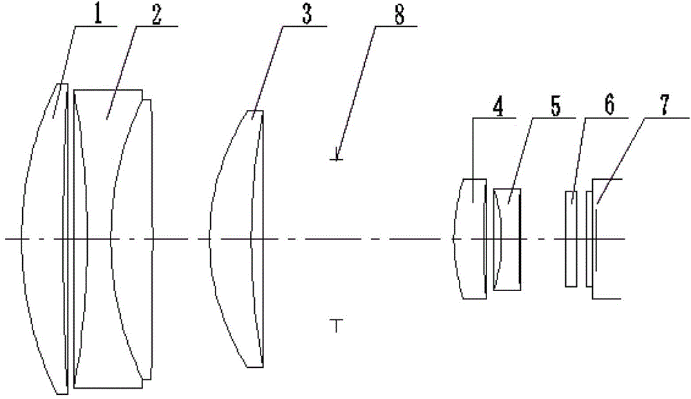
[0030] refer to figure 1 As shown, a wavelength-band switchable broadband confocal detection optical system consists of a first spherical lens 1, a second spherical lens 2, a third spherical lens 3, a fourth spherical lens 4, and a fifth spherical lens 5 and a parallel plate glass 6, the order of the optical materials of the first spherical lens 1, the second spherical lens 2, the third spherical lens 3, the fourth spherical lens 4, and the fifth spherical lens 5 is as follows: ZK10, ZF6 and ZK6 (doublet lens), LAF5, ZK6, ZF6, while the first spherical lens 1 is a convex-concave positive lens, the second spherical lens 2 is a negative positive doublet lens, and the third spherical lens 3 is a convex-concave lens Positive lens, the fourth spherical lens 4 is a convex-concave positive lens, the fifth spherical lens 5 is a concave-convex negative lens, the material of the parallel flat glass 6 is ordinary glass K9, and the parallel flat glass 6 is located on the fifth lens 5 and ...
PUM
 Abstract
Description
Claims
Application Information
 - R&D
- Intellectual Property
- Life Sciences
- Materials
- Tech Scout
- Unparalleled Data Quality
- Higher Quality Content
- 60% Fewer Hallucinations
Browse by: Latest US Patents, China's latest patents, Technical Efficacy Thesaurus, Application Domain, Technology Topic, Popular Technical Reports.
© 2025 PatSnap. All rights reserved.Legal|Privacy policy|Modern Slavery Act Transparency Statement|Sitemap|About US| Contact US: help@patsnap.com