Lighting system for automatic optic inspection and combination of lighting system and image system

An automatic optical detection and lighting system technology, applied in the field of lighting system and its combination with imaging system, can solve problems such as large space optical path, achieve the best imaging quality and reduce the space effect

Inactive Publication Date: 2012-05-16
MACHVISION INC
View PDF4 Cites 7 Cited by
  • Summary
  • Abstract
  • Description
  • Claims
  • Application Information

AI Technical Summary

Problems solved by technology

[0005] The above-mentioned existing technologies all use curved reflectors or refractors to concentrate

Method used


Image

  • Lighting system for automatic optic inspection and combination of lighting system and image system
  • Lighting system for automatic optic inspection and combination of lighting system and image system
  • Lighting system for automatic optic inspection and combination of lighting system and image system

Examples


Embodiment Construction

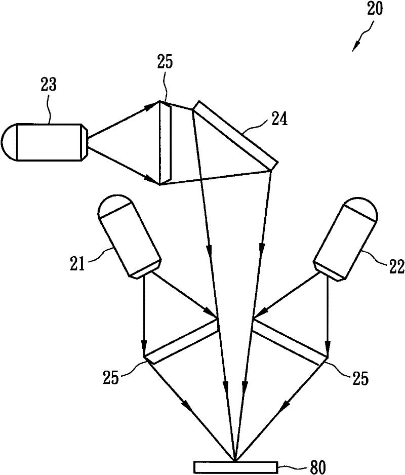
[0037] figure 2 It is a schematic diagram of an illumination system 20 for automatic optical inspection according to an embodiment of the present invention, illuminating an object 80 to be inspected, which includes a first light source 21, a second light source 22, a third light source 23, a The first optical element 24 and at least three second optical elements 25 . Each of the second optical elements 25 is respectively arranged on the light output ends of the first light source 21, the second light source 22 and the third light source 23, and can directly or indirectly concentrate the light output by each light source on the object to be detected. An axis on the surface of object 80 . The light output ends of the first light source 21 and the second light source 22 are symmetrically directed to the surface of the object, and the light sources 21-23 are an LED linear light source or a fiber optic linear light source. In addition, the first optical element 24 is roughly ali...


PUM


Abstract

The invention discloses a lighting system for automatic optic inspection and a combination of the lighting system and an image system, the lighting system is used for lighting an object to be detected and comprises a first light source, a second light source, a third light source, a first optical element and at least three second optical elements. The second optical elements are respectively arranged at the light output ends of the first light source, the second light source and the third light source and can centralize the light rays output by each light source. The light output ends of the first light source and the second light source symmetrically point to the surface of an object; the first optical element is aligned with the symmetrical surface and can guide the light ray which is output by the third light source to the surface of the object. In the invention, the total length of optical path length of light can be reduced and the space needed by the lighting system is effectively reduced.

Description

technical field [0001] The invention relates to an illumination system for automatic optical inspection and its combination with an imaging system, in particular to a light source system for illuminating the surface of an object to be inspected. Background technique [0002] Automated optical inspection (AOI) is a key step in the manufacture of liquid crystal displays, semiconductor integrated circuit chips, and circuit boards. It is used to diagnose and improve product quality in the manufacturing process, thereby reducing manufacturing costs. The basic performance of automated optical inspection is measured by two key indicators: inspection speed and inspection sensitivity. Due to the advancement of production technology, the manufacturing speed is accelerated, the size of the substrate is increased, and the size of the printed pattern is reduced, so higher requirements are placed on the speed and sensitivity of automatic optical inspection. [0003] The light intensity r...

Claims


Application Information

Patent Timeline
IPC IPC(8): F21S8/00F21V13/00G01B11/00G02B27/10G02B3/08
Inventor 汪光夏陈辉毓曾恕威
Owner MACHVISION INC
Why Eureka
Try Eureka