Polaroid and manufacturing methods of display panel and polaroid

A manufacturing method and display panel technology, applied in the direction of optics, polarizing elements, nonlinear optics, etc., can solve the problems of inability to complete the glass cutting process, increase the workload of operators, and inability to use stress cutting, etc., so as to reduce the number of attachments, The effect of reducing attachment time and reducing workload

Inactive Publication Date: 2012-12-19
BOE TECH GRP CO LTD
View PDF5 Cites 7 Cited by
  • Summary
  • Abstract
  • Description
  • Claims
  • Application Information

AI Technical Summary

Problems solved by technology

[0003] In the existing liquid crystal cell forming process, the liquid crystal cell formed after laminating the array substrate and the color filter substrate needs to be cut into a plurality of display panels according to a certain size, and after grinding, cleaning, etc. A layer of polarizer is attached to the upper and lower surfaces. This is because the cutting process of the glass (that is, the base material in the array substrate and the color filter substrate) uses a micro-knife wheel to cut into the brittle glass, and slides and splits according to the effect of stress. , while the polarizer is not made of brittle materials, but is made of organic elastic materials, which cannot be cut by stress
That is, if the entire polarizer is first attached to the upper and lower sides of the liquid crystal cell and then cut into multiple display panels together with the entire polarizer and the liquid crystal cell, the cutting process of the glass cannot be completed (if rough cutting Cutting the display panel by cutting the polarizer will damage the glass)
That is to say, if the liquid crystal cell needs to be cut into n display panels, polarizers need to be attached 2n times, and it takes 5 to 10 seconds for each polarizer to be attached. It can be seen that when the number of times of attaching polarizers When it is more, it takes more time, and it also increases the workload of the operator

Method used


Image

  • Polaroid and manufacturing methods of display panel and polaroid
  • Polaroid and manufacturing methods of display panel and polaroid
  • Polaroid and manufacturing methods of display panel and polaroid

Examples


Embodiment 1

[0061] In this embodiment, the polarizer includes a base and a polarizing film layer arranged on the base, the polarizing film layer includes a plurality of unit polarizing film layers, and the positions of the plurality of unit polarizing film layers on the base and The positions of multiple display panels in the liquid crystal cell (the liquid crystal cell can be divided into multiple display panels, and the liquid crystal cell has not been cut here) correspond to the positions respectively, and the area of ​​the polarizing film layer of each unit is less than or equal to its corresponding display The area of ​​the panel is larger than the area of ​​the corresponding effective display area of ​​the display panel (the display panel can be divided into an active area (A / A, active area) and a peripheral area). Preferably, the distance between every two unit polarizing film layers 3 a is 5 mm to 20 mm.

[0062] This embodiment also provides a method for manufacturing a display p...

Embodiment 2

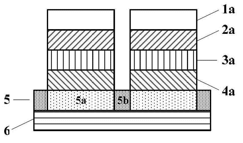
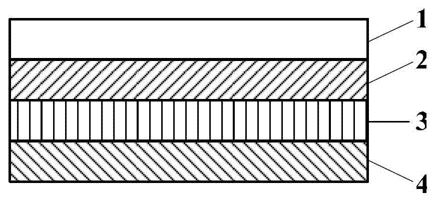
[0069] like figure 1 As shown, in this embodiment, the polarizer includes a surface protection layer, a first polarizing film protective layer, a polarizing film layer, a second polarizing film protective layer, a substrate 5 and a peeling layer (i.e. figure 1 The first peeling layer in 6).

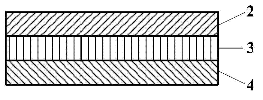
[0070] The polarizing film layer includes a plurality of unit polarizing film layers 3a, the plurality of unit polarizing film layers 3a correspond to the positions of a plurality of display panels in the liquid crystal cell respectively, and the area of ​​each unit polarizing film layer 3a is less than or equal to its corresponding to the area of ​​the display panel. Preferably, the distance between every two unit polarizing film layers 3a is 5 mm to 20 mm (ie Figure 4 Dimension d) in (b).

[0071] The first polarizing film protective layer and the second polarizing film protective layer are respectively attached to both sides of the polarizing film layer; the first polarizing film p...

Embodiment 3

[0105] The difference between the polarizer described in this embodiment and Embodiment 2 is:

[0106] The polarizer also includes a first adhesive layer and a functional film layer, the functional film layer is used to increase the intensity of transmitted light, or to increase the intensity of reflected light, or to compensate for optical phase difference, or to increase both the intensity of transmitted light Intensity in turn increases the reflected light intensity. Preferably, the functional film layer is an anti-reflective film, a reflective film, a phase compensation film or a semi-transparent and semi-reflective film. The first adhesive layer and the functional film layer are sequentially arranged between the second polarizing film protective layer 4 and the substrate 5, that is, the first adhesive layer is attached to the second polarizing film protective layer 4 on the side away from the polarizing film layer 3 , the functional film layer is attached on the side of ...


PUM

PropertyMeasurementUnit
wavelengthaaaaaaaaaa
thicknessaaaaaaaaaa

Abstract

The invention provides a polaroid. The polaroid comprises a substrate and a polarizing film layer arranged on the substrate; the polarizing film layer comprises a plurality of unit polarizing film layers; the positions of the plurality of unit polarizing film layers on the substrate correspond to the positions of a plurality of display panels in a liquid crystal box; and the area of each unit polarizing film layer is less than or equal to that of the corresponding display panel. Correspondingly, the invention further provides a manufacturing method of the display panel by using the polaroid and a manufacturing method of the polaroid. The polaroid disclosed by the invention is applied to a liquid crystal box-forming technology, and the attaching number of times and the attaching time of the polaroid can be greatly reduced.

Description

technical field [0001] The invention belongs to the field of display technology, and in particular relates to a polarizer, a method for manufacturing a display panel using the polarizer, and a method for manufacturing the polarizer. Background technique [0002] The manufacturing process of the liquid crystal display panel generally includes an array (Array) process, a liquid crystal cell (Cell) process and a module (Module) process. [0003] In the existing liquid crystal cell forming process, the liquid crystal cell formed after laminating the array substrate and the color filter substrate needs to be cut into a plurality of display panels according to a certain size, and after grinding, cleaning, etc. A layer of polarizer is attached to the upper and lower surfaces. This is because the cutting process of the glass (that is, the base material in the array substrate and the color filter substrate) uses a micro-knife wheel to cut into the brittle glass, and slides and splits...

Claims


Application Information

Patent Timeline
Patent Type & Authority Applications(China)
IPC IPC(8): G02F1/1335G02F1/1333G02B5/30
Inventor 朱剑磊
Owner BOE TECH GRP CO LTD
Why Eureka
Try Eureka