

Chopper circuit for power generator exciting current
A technology of excitation current and chopper circuit, which is applied to control the direction of the generator through the change of the magnetic field, can solve the problems of slow turn-off process of the field effect tube V1, long turn-off time, and large loss of the field effect tube V1, and shorten the turn-off The effect of shortening the turn-off time, accelerating the turn-off process, and reducing loss
Inactive Publication Date: 2012-12-19
BEIJING SHUGUANG AERO ELECTRICAL
View PDF4 Cites 3 Cited by
- Summary
- Abstract
- Description
- Claims
- Application Information
AI Technical Summary
Problems solved by technology
Its disadvantages are: due to the resistance limitation of resistor R1, the turn-off process of FET V1 is slow and the turn-off time is long, resulting in large loss of FET V1
Method used
View moreImage
Smart ImageViewing Examples

Examples
Embodiment 1
[0013] Example 1, the resistance of R1 and R2 is 20Ω, the resistance of R3 is 5.1KΩ, the model of D1 is 2CN3F, the model of V1 is IXKK85N60C, the DS voltage is 150V when the field effect tube V1 is turned off, and the average current of V1 is 20A. The turn-off time of the field effect tube is reduced from 100ns to 55ns.
Embodiment 2
[0014] Example 2: The resistance of R1 and R2 is 100Ω, the resistance of R3 is 5.1KΩ, the model of D1 is 2CN3F, the model of V1 is IRF460, the DS voltage is 110V when the field effect tube V1 is turned off, and the average current of V1 is 5A. The turn-off time of the field effect tube is reduced from 51ns to 30ns.
Login to View More PUM
 Abstract
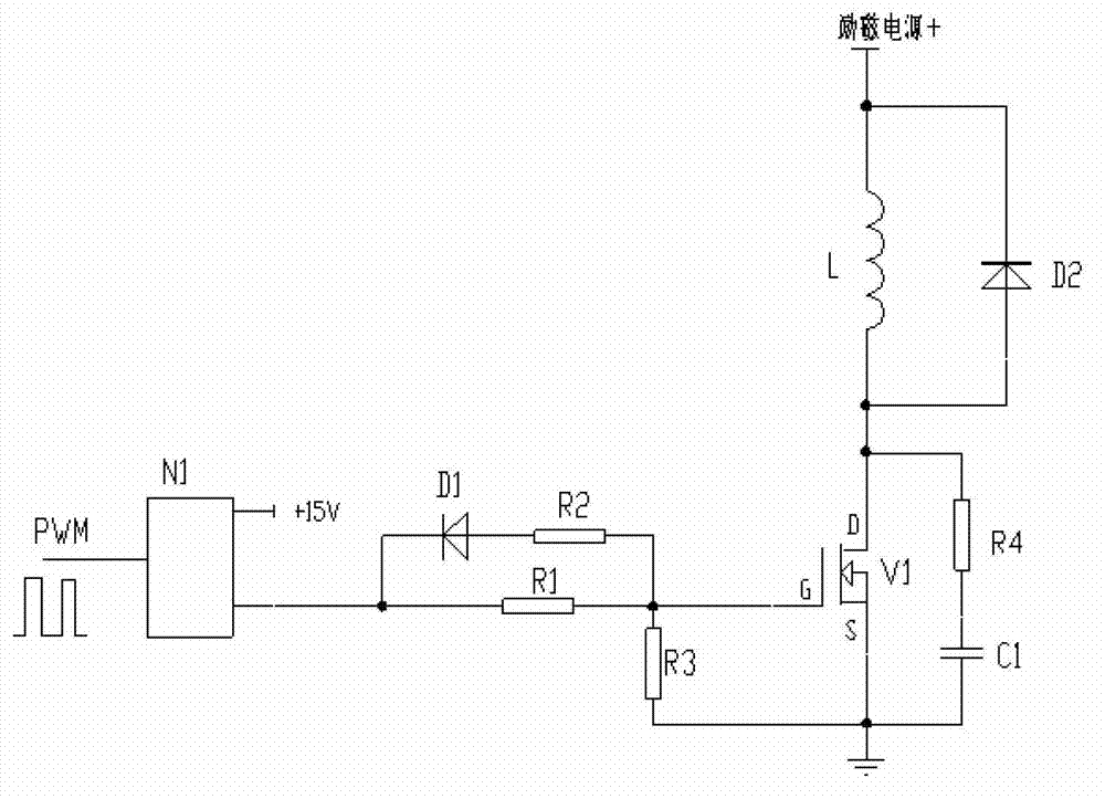
The invention belongs to the design technology of power generator controllers and relates to an improvement of a chopper circuit for power generator exciting current. The chopper circuit comprises a driving chip N1, a resistor R1, a resistor R3, a resistor R4, a field-effect tube V1, a capacitor C1 and a diode D2; the chopper circuit is characterized by also comprising a second series branch consisting of a diode D1 and a resistor R2 which are connected in series, the negative electrode of the diode D1 is connected with the output end of the driving chip N1, and the other end of the resistor R2 is connected with the grid electrode G of the field-effect tube. According to the chopper circuit, the switching-off process of the field-effect tube V1 is accelerated, the switching-off time is reduced, so that the loss of the field-effect tube V1 is reduced.
Description
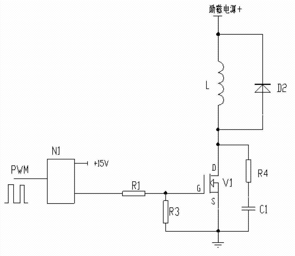
technical field [0001] The invention belongs to the design technology of a generator controller and relates to the improvement of a generator excitation current chopper circuit. Background technique [0002] The active aircraft power system is basically composed of a generator and a controller. The controller realizes functions such as voltage regulation and protection of the generator output voltage. When the load changes, the controller keeps the output voltage of the generator constant by adjusting the excitation current of the generator. Regulating the excitation current is realized by driving the switching tube in the excitation current loop to be turned on and off by the chopping signal. The current structure of a generator excitation current chopper circuit can be found in figure 1 , which is composed of driver chip N1, resistors R1, R3 and R4, field effect transistor V1, capacitor C1 and diode D2; diode D2 is connected in parallel at both ends of generator excitati...
Claims
Login to View More Application Information
Patent Timeline
 Patent Type & AuthorityApplications(China)
IPC IPC(8): H02P9/30
Inventor赵雅周
OwnerBEIJING SHUGUANG AERO ELECTRICAL