Edge detection method and device for constant envelope same frequency interference

An edge detection device and a technology for co-channel interference, which are applied in the field of edge detection technology for co-channel interference, can solve problems such as affecting the performance of an equalization module, and achieve the effect of improving demodulation performance.

Active Publication Date: 2015-05-20
LEADCORE TECH
4 Cites 0 Cited by

AI-Extracted Technical Summary

Problems solved by technology

[0003] The inventors of the present invention found that using the existing SAIC method, in the case of synchronous and co-frequency coverage, some signal gain can be obtained, but it is not applicable to the ...

Method used

[0055] In step 101, DC elimination is performed before phase derotation, thereby o...

Abstract

The invention discloses an edge detection method and a device for constant envelope same frequency interference. The method comprises the following steps of: firstly recovering training sequence domain data of the cell, calculating average power of cell training sequence domain data; calculating power distribution of the received signals; obtaining power distribution of interference signals through obtaining difference values between the distributed power values and the average power of the cell training sequence domain data; and according to the power distribution of the interference signals, regarding a position with the maximal power change difference as a constant envelope edge position. The constant envelope edge position can express the characteristics of terminal signals and the interference signals at the constant envelope edge two sides for the received signals under asynchronous same frequency interference. Therefore, the method and the device are beneficial to a balance module to adopt different information channel estimation policies and data demodulation policies to different areas, and a demodulation performance of the balance module is improved.

Application Domain

Transmission monitoringTransmitter/receiver shaping networks +1

Technology Topic

VIT signalsEdge detection +4

Image

  • Edge detection method and device for constant envelope same frequency interference
  • Edge detection method and device for constant envelope same frequency interference
  • Edge detection method and device for constant envelope same frequency interference

Examples

  • Experimental program(1)

Example Embodiment

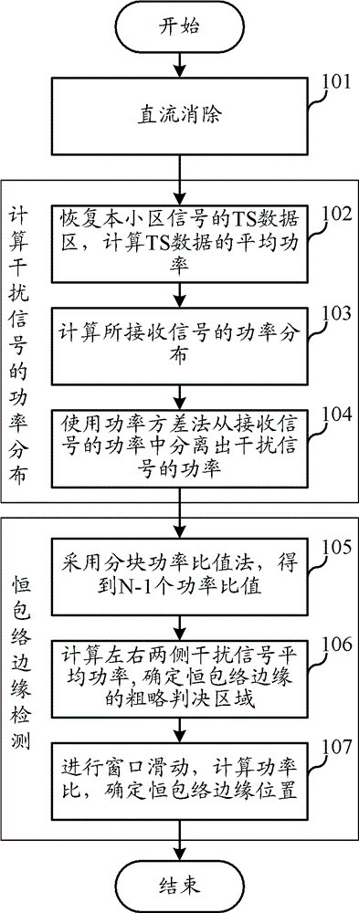
[0052] In order to make the purpose, technical solution and advantages of the present invention clearer, the following will further describe the implementation of the present invention in detail in conjunction with the accompanying drawings.
[0053] The first embodiment of the present invention relates to a constant-envelope co-frequency interference edge detection method. The position of the constant-envelope edge can be accurately found in the asynchronous co-frequency interference, which reflects the position of the received signal on both sides of the constant envelope edge under asynchronous co-frequency interference. The characteristics of the terminal signal and the characteristics of the interference signal, so that different strategies can be adopted according to the edge detection results, which is beneficial for the equalization module to demodulate data in different regions and improve the demodulation performance of the equalization module.
[0054] The specific process is as figure 1 shown.
[0055] In step 101, DC elimination is performed before phase derotation, so as to overcome the adverse effect of residual DC on constant envelope edge calculation.
[0056] In step 102 to step 104, the power distribution of the interference signal is calculated.
[0057] By calculating the power distribution of the received signal, subtracting the average power of the TS data in the cell and taking the absolute value, the power distribution of the interference signal is obtained. details as follows:
[0058] In step 102, the TS data area of ​​the signal of the local cell is recovered, and the average power of the TS data is calculated.
[0059] Specifically, using the known TS sequence S of the cell n+1-j , and the signal impulse response h of the local cell obtained according to the correlation calculation j , to perform convolution calculation on the two, that is, the TS data of the signal of the local cell can be recovered, and then the average power of the TS data can be calculated.
[0060] The signal passes through the air interface, which is equivalent to a convolution process. Therefore, when we restore the signal, we use the local training sequence S n+1-j and the channel impulse response h j Do the convolution.
[0061] Convolution calculation formula:
[0062] In step 103, the power distribution of the received signal is calculated. That is, the power of every n bits in the received signal is calculated separately to obtain the power distribution of the received signal, where n is greater than or equal to 1, and n is set to 1 in this embodiment. That is, the power of each bit of the received signal is calculated to obtain the power distribution of the received signal.
[0063] In step 104, the power of the interference signal is separated from the power of the received signal using the power variance method.
[0064] Specifically, assuming that the received data is r, the transmitted data is x, through a channel h with a memory length of L, and the channel noise is n, then r=x·h+n, the mathematical expectation of the received data power is:
[0065] E{|r| 2}=E{x h+n| 2}
[0066] =E{|x·h| 2 +|n| 2 +2Re(x·h·n * )}
[0067] =E{|x·h| 2}+σ 2
[0068] It is assumed that the training sequences of each co-frequency signal have relatively good correlation and the Gaussian white noise is also small, and the training sequence and Gaussian white noise of each co-frequency signal are also very small. Then σ 2 will mainly contain the power of the interfering signal.
[0069] That is to say, assuming that the average power of the recovered TS data in the local cell is equal to the average power of the local cell signal in the received signal, the power of each bit of the received signal is subtracted from the average power of the TS data and the absolute value is obtained, that is, Get the power distribution of the interfering signal. At this point the constant envelope edge is already apparent.
[0070] Calculation formula:
[0071] where POW_Data i is the power of each bit of the received signal; As the average power of the recovered TS data of the own cell, it is assumed that it is equal to the average power of the signal of the own cell in the received signal.
[0072] From step 105 to step 107, constant envelope edge detection is performed according to the power distribution of the interference signal, and the position with the largest difference in power variation is taken as the constant envelope edge position.
[0073] In step 105, block the interference signal (that is, the calculated interference signal power distribution), divide it into N blocks, calculate the average power of each block interference signal, and use the block power ratio method to divide the interference signal of the front and rear two blocks The average power is compared to the power ratio, and the small power is compared to the high power, and the correction factor method is used to obtain N-1 power ratios.
[0074] In this step, the division into blocks should be reasonable, generally adopting the division method of 12 blocks*12 bits or 24 blocks*6 bits. Taking 12 blocks as an example, the power ratio of the two blocks before and after is multiplied by a correction factor to obtain 11 power ratios. This correction factor is used to increase the reliability of the judgment result and improve the accuracy. It is generally not omitted, but not necessarily omitted.
[0075] The calculation formula is: R i = min ( P 1 , P 2 ) max ( P 1 , P 2 ) , 1 | P 2 - P 1 | , The correction factor is:
[0076] In step 106, select the three smallest ones from the above-mentioned N-1 power ratios (indicating that the power variation in the 24-bit area is more obvious), obtain their signal block position areas respectively, and use the characteristics of the constant envelope of the interference signal to calculate the The average power of the interference signal on the left and right sides of the position is calculated by comparing the small power of the two average powers with the high power to obtain a power ratio. A total of 3 power ratios are obtained, and the smallest one is selected from the three. The corresponding signal block position area is used as the rough decision area of ​​the envelope edge.
[0077] For example, figure 2 Shows an air interface receiving data waveform, which is the smallest when calculating the ratio of the third block (the average power ratio of the interference signal between the third signal block and the fourth signal block), indicating that the waveform is in the range of [36, 60] bits There are large mutations. Therefore, the average power of the interference signal of [0, 2] 3 blocks is taken on the left, and the average power of the interference signal of [5, 10] 6 blocks is taken on the right, and the average power of the left and right sides is compared.
[0078] The calculation formula is:
[0079]
[0080] The above formula considers the method of calculating the average power of left and right interference signals when the primary selection point is in the general position signal block, and when the primary selection point is in the first block and the last block.
[0081] In this step, the three smallest ones are selected from the N-1 power ratios, and the power ratios of the left and right interference signals are calculated. In practical applications, two or four can also be selected for calculation and comparison.
[0082] In step 107, the rough judgment area (2 signal blocks, 24 bits in total) is subjected to window sliding of 4 bits in length, sliding 1 bit at a time, sliding n times in total, and calculating the two interference signals before and after sliding respectively. Average power, compare small power to high power to get a power ratio, multiply it by a correction factor, and get n power ratios in total, choose the smallest one from the n power ratios, and the sliding position corresponding to the smallest power ratio, It is a more accurate constant envelope edge position.
[0083] Since the rough judgment area may be at the front end, the end end, or the middle area of ​​the 12 blocks, the number of sliding windows is different for different situations. For the case where the rough judgment area is in the middle, the number n of window sliding should be 24; for the case where the rough judgment area is at the front or the end, the number n of window sliding should be 16 times.
[0084] Calculation formula: R i = min ( P i , P i + 4 ) max ( P i , P i + 4 ) , 1 | P i + 4 - P i |
[0085] in P i = Σ i i + 3 Power _ Data [ i ] is the characteristic window power value of 4 bits; R i = min ( P i , P i + 4 ) max ( P i , P i + 4 ) · 1 | P i + 4 - P i | Perform a power ratio for the two feature windows before and after sliding, and multiply by the correction factor
[0086] In this step, the length of the sliding window is 4 bits, and the length of each sliding is 1 bit, because according to actual calculations, its estimation accuracy and calculation amount are relatively ideal, which can better guarantee the estimation accuracy of the boundary position, but this does not It is not necessary, and a slight change in the length of the sliding window and the length of each sliding can also solve the technical problem of the present invention, which is also within the protection scope of the present invention.
[0087] It should be noted that, in this embodiment, in order to reduce the amount of calculation, step 105 and step 106 preliminarily determine the decision regions of the two signal blocks according to the minimum ratio. Moreover, due to the randomness of air interface signal superposition, step 106 can help increase the probability of reliability. In practical applications, the above two steps can also be omitted, and the window power sliding method is directly performed on the interference signal; or, one of the steps is omitted, such as step 106 is omitted, and the minimum three power ratios calculated in step 105 are directly calculated The corresponding signal block is subjected to the window power sliding method to obtain the edge position of the constant envelope.
[0088] To sum up, the power distribution of the interference signal can be obtained by calculating the difference between each power value of the received signal distribution and the average power of the TS data in the cell; position as the constant envelope edge position. The constant envelope edge position can reflect the characteristics of the terminal signal and the interference signal of the received signal on both sides of the constant envelope edge under asynchronous and co-frequency interference, which is conducive to the equalization module adopting different channel estimation strategies and data for different regions. Demodulation strategy to improve the demodulation performance of the equalization module.
[0089] The second embodiment of the present invention relates to a constant-envelope co-channel interference edge detection device, such as image 3 shown, including:
[0090] The TS average power calculation module is used to restore the TS data of the cell and calculate the average power of the TS data of the cell;
[0091] The received signal power calculation module is used to calculate the power distribution of the received signal;
[0092] The interference signal power calculation module is used to calculate the difference between the power of each part of the received signal and the average power of the TS data in the cell to obtain the power distribution of the interference signal;
[0093] The constant envelope edge position determination module is configured to use the position with the largest power variation difference as the constant envelope edge position according to the power distribution of the interference signal.
[0094] Wherein, the TS average power calculation module may further include the following submodule: a submodule for recovering the TS data of the local cell by convolving the training sequence of the local cell and the signal impulse response of the local cell.
[0095] The received signal power calculation module may further include the following submodules: respectively calculate the power of every n bits in the received signal to obtain the power distribution of the received signal; n is greater than or equal to 1. Preferably n is 1 bit.
[0096] The interference signal power calculation module may further include the following submodules: respectively subtract the average power of the TS data in the cell from the power of each bit in the received signal, and take the absolute value to obtain the power distribution of the interference signal.
[0097] The constant envelope edge position determination module can further include the following submodules:
[0098] The block power ratio sub-module is used to divide the interference signal into N blocks on average, calculate the average power of each block of interference signals, and perform power ratios on the average power of the two interference signals before and after, and compare the low power to the high power, and N-1 power ratios are obtained by multiplying by a correction factor; the correction factor is the reciprocal of the difference between the two powers for which power ratios are performed. The block power ratio sub-module may divide the interference signal into 12×12-bit signal blocks; or, 24×6-bit signal blocks.
[0099] The left and right power ratio sub-modules are used to select the smallest x from the N-1 power ratios, respectively obtain the location areas of the signal blocks corresponding to the x power ratios, and calculate the average power of the interference signals on the left and right sides of the location area, and set Among the two calculated average powers, the small power is higher than the high power, and a power ratio is obtained. A total of x power ratios are obtained, and the smallest power ratio is selected from the x power ratios, and the corresponding signal block location area is used as a constant envelope A rough decision area at the edge of the network; x is any integer from 2 to 4, and x is preferably 3.
[0100] The sliding window sub-module is used to slide the window of y-bit length on the rough judgment area, slide d bits each time, calculate the average power of the two interference signals before and after sliding, and compare the small power to the high power to obtain A power ratio is multiplied by a correction factor to obtain m power ratios in total, and the smallest one is selected from the m power ratios, and the sliding position corresponding to the smallest power ratio is used as the edge position of the constant envelope. Wherein, the window length y may be 4 bits, and the sliding length d may be 1 bit.
[0101] The above scheme is a preferred embodiment of the present invention. In practical applications, the block power ratio submodule and/or the left and right power ratio submodule can also be omitted, and the sliding window submodule can directly perform window sliding and power of y bit length on the interference signal. ratio calculation; or the sliding window submodule can also perform window sliding of y bit length on the signal blocks corresponding to the smallest t power ratios among the N-1 power ratios calculated by the block power ratio submodule, and t is 1 to 4 any integer in . The technical problem of the present invention can also be solved and the effect of the present invention can be achieved.
[0102] In summary, the constant envelope edge position determined by the edge detection device for constant envelope co-frequency interference in this embodiment can reflect the characteristics and The characteristics of the interference signal are beneficial to the equalization module to adopt different channel estimation strategies and data demodulation strategies for different regions, and improve the demodulation performance of the equalization module.
[0103] Although the present invention has been illustrated and described with reference to certain preferred embodiments thereof, it will be understood by those skilled in the art that various changes in form and details may be made therein without departing from the present invention. The spirit and scope of the invention.

PUM

no PUM

Description & Claims & Application Information

We can also present the details of the Description, Claims and Application information to help users get a comprehensive understanding of the technical details of the patent, such as background art, summary of invention, brief description of drawings, description of embodiments, and other original content. On the other hand, users can also determine the specific scope of protection of the technology through the list of claims; as well as understand the changes in the life cycle of the technology with the presentation of the patent timeline. Login to view more.

Similar technology patents

Transmission processing method and device of downlink control channel

ActiveCN108737018AImprove demodulation performanceImprove overlay performance
Owner:POTEVIO INFORMATION TECH

Demodulator and demodulating method for high-speed data packet access system

ActiveCN101626361AImprove demodulation performanceEase of hardware implementation
Owner:SANECHIPS TECH CO LTD

Data interleaving method and device

InactiveCN108880740AFacilitate error correction and data recoveryImprove demodulation performance
Owner:HUAWEI TECH CO LTD

A mixed-path processing method in CDMA system

InactiveCN101167287BImprove demodulation performance
Owner:ZTE CORP

A retransmission method in a cluster system

ActiveCN108990098AImprove demodulation performance
Owner:CHENGDU TD TECH LTD

Classification and recommendation of technical efficacy words

  • Improve demodulation performance

Method, base station and subscriber terminal for obtaining scheduling control information in high speed grouping access

InactiveCN101155392AImprove demodulation performanceReduce the probability of collision
Owner:CHINA ACAD OF TELECOMM TECH

Method and device for processing baseband data

ActiveCN102316056AExpand the scope of statisticsImprove demodulation performance
Owner:ZTE CORP

Demodulator and demodulating method for high-speed data packet access system

ActiveCN101626361AImprove demodulation performanceEase of hardware implementation
Owner:SANECHIPS TECH CO LTD

Transmission processing method and device of downlink control channel

ActiveCN108737018AImprove demodulation performanceImprove overlay performance
Owner:POTEVIO INFORMATION TECH

Data interleaving method and device

InactiveCN108880740AFacilitate error correction and data recoveryImprove demodulation performance
Owner:HUAWEI TECH CO LTD
Why Eureka
Try Eureka