Artificial auditory ossicle for treating mixed hearing damage
A hearing-impaired and hybrid technology, applied in medical science, prosthesis, etc., can solve the problem of electromagnetic actuators with narrow working frequency band, unsuitable for fully implanted artificial ossicles, and high energy consumption of electromagnetic actuators. problem, to achieve the effect of easy to widely popularize and use, simple structure and low power consumption
- Summary
- Abstract
- Description
- Claims
- Application Information
AI Technical Summary
Problems solved by technology
Method used
Image
Examples
Embodiment 1
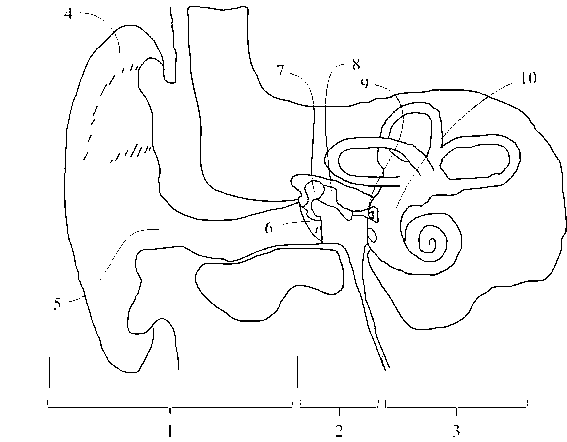
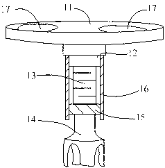
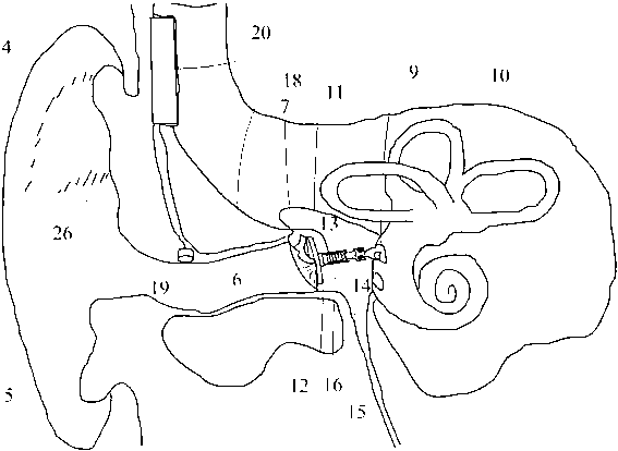
[0032] Such as figure 2 image 3 As shown, the artificial ossicles of the present invention for the treatment of mixed hearing loss include a top plate 11 implanted on the inner eardrum 6 of the human ear. Electric device, the piezoelectric device includes a stepped connecting rod 12, a sleeve 16 sleeved on the connecting rod 12, a piezoelectric stack 13 is arranged inside the sleeve 16, and the outlet side of the sleeve 16 is provided with a pressure The electrical stack 13 abuts against the tray 15 on the connecting rod 12 . The tray 15 is slidingly fitted with the sleeve 16 . The front part of the piezoelectric device is provided with a stapes clamp 14 acting on the stapes 9 of the human ear; the connecting rod 12 is connected eccentrically to the top plate 11, and the connection point is close to the side of the long diameter of the top plate. There are 4-5 through holes 17 on the top plate 11; the stapes clamp 14 is in the shape of a funnel clamp, a herringbone with a...
Embodiment 2
[0040] Such as Figure 4 As shown, it is basically the same as Embodiment 1, and the similarities are omitted. The difference: the piezoelectric device includes a connecting rod 12 of a cylindrical articulated head, an end cover 21 hinged on the connecting rod 12, a sleeve 16 is arranged on the end cover 21, and a piezoelectric stack is arranged inside the sleeve 16. The exit side of the stack 13 , the bushing 16 , is provided with a tray 15 holding the piezoelectric stack 13 against the connecting rod 12 . The connecting rod 12 and the piezoelectric component are connected by a spherical pair, and the connecting rod 12 is connected to the connecting rod 12 through the spherical pair 22 through the end cover 21, so as to realize the spherical pair connection between the connecting rod 12 and the piezoelectric component.
Embodiment 3
[0042] Such as Figure 5 As shown, it is basically the same as Embodiment 1, and the similarities are omitted. The difference: the piezoelectric device includes a connecting rod 12 of a spherical joint, a housing 23 hinged on the connecting rod 12, a piezoelectric stack 13 is arranged inside the housing 23, and a connecting rod 13 is provided at the bottom of the housing 23. The connecting sleeve 25 of the stapes clamp 14. The connecting rod 12 and the piezoelectric member are connected by a spherical pair, and the ball head 24 is connected with the connecting rod 12 of the spherical joint, so as to realize the spherical pair connection between the connecting rod 12 and the piezoelectric member. The housing 23 adopts a cymbal structure, and the two top ends of the piezoelectric stack 13 in the telescopic direction are fixed on the left and right walls of the housing 23, so as to convert the lateral telescopic movement of the piezoelectric stack 13 into the longitudinal moveme...
PUM
 Abstract
Description
Claims
Application Information
 - R&D
- Intellectual Property
- Life Sciences
- Materials
- Tech Scout
- Unparalleled Data Quality
- Higher Quality Content
- 60% Fewer Hallucinations
Browse by: Latest US Patents, China's latest patents, Technical Efficacy Thesaurus, Application Domain, Technology Topic, Popular Technical Reports.
© 2025 PatSnap. All rights reserved.Legal|Privacy policy|Modern Slavery Act Transparency Statement|Sitemap|About US| Contact US: help@patsnap.com


