Continuous stirring granulator

A technology of granulator and granulation chamber, which is applied in the direction of granulation in static tanks/troughs, etc., which can solve problems such as flying dust, polluting the environment, and wide particle size distribution of products, so as to reduce material loss, reduce dust flying, and produce The effect of stable quality

Inactive Publication Date: 2012-12-26
刘广文
View PDF6 Cites 5 Cited by
  • Summary
  • Abstract
  • Description
  • Claims
  • Application Information

AI Technical Summary

Problems solved by technology

[0003] In the granulation process, the main purpose of granulation is to obtain the required uniform and narrow particle size distribution. However, for many years, the particle size distribution of this equipment product is wide, and the production mode of intermittent production limits the purpose of granulation. There are three disadvantages
First of all, intermittent production, open feeding method, low production efficiency, serious dust flying, causing a large amount of material loss, polluting the environment and endangering human health
Secondly, the product particle size distribution is wide, which affects product quality
The third is that the particle size and hardness of the product cannot be controlled. For some particles, the product particle size and hardness directly affect the product quality, and the inability to control the product particle size and hardness also limits the use of such equipment

Method used


Image

  • Continuous stirring granulator
  • Continuous stirring granulator

Examples


Embodiment Construction

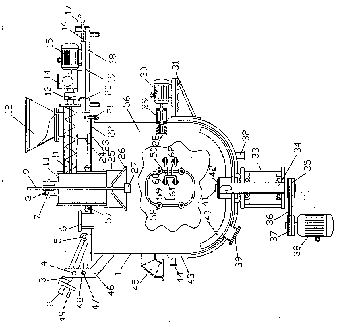
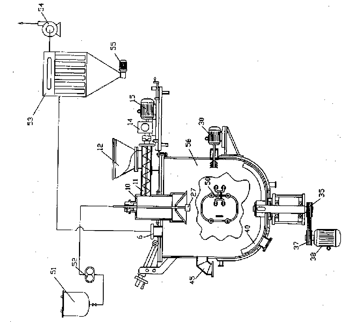
[0019] A continuous stirring granulator, including a liquid tank 51, a pressurized pump 52, a bag filter 53, an induced draft fan 54, a feeding hopper 12, a screw feeder 11, a granulation chamber 56, an exhaust pipe 6, and a feeding circle Barrel 10, powder distribution cone 26, atomizer 27, stirring paddle 40, crushing flying knife group 28. The liquid tank 51 and the booster pump 52 with a pressure of 1.24Mpa and a flow rate of 1L / min are connected to the atomizer 27 through pipelines, and the bag filter 53 and the air volume are 70-100m 3 The induced draft fan 54 of / h is connected to the exhaust pipe 6 through the air duct, and a star valve 55 is installed under the bag filter 53 .

[0020] The granulation chamber 56 is a cylindrical body 1 with a bottom arc shape, a flange 22 at the upper end, a diameter of 0.6 m, and a height of 0.6 m. The flange 22 at the upper end of the cylindrical body 1 is provided with a loam cake 23, and the loam cake 23 is connected with flange ...


PUM


Abstract

The invention relates to a continuous stirring granulator. A granulating chamber is a cylinder body. An upper cap is arranged on the upper end of the cylinder body. A feeding cylinder extending to the granulating chamber is arranged at the center of the upper cap. An atomizer is connected to the lower end of a feeding pipe and extends into the granulating chamber with the feeding cylinder. One side of the feeding cylinder is connected with a spiral feeding device. The upper cap has a planar sealing structure, and is compacted by using a handwheel compactor. A fixed shaft is arranged on one side of the upper cap. A rotatable screw is sleeved on the fixed shaft. A pair of supporting seats is welded on the outer side of the cylinder body. A transverse shaft is arranged on the upper part of the supporting seats. A slide block is sleeved on the transverse shaft. A nut handle is arranged on a screw sleeved on the slide block. One end of a pair of lugs welded on the upper cap penetrates the fixed shaft below the supporting seat. The nut handle is rotated, such that the upper cap is rotationally opened with the supporting seats as a center under driving. According to the invention, stirring blades rapidly stir a powder material. After a proper amount of liquid is added, continuous stirring granulation can be carried out, such that production process is shortened. Therefore, manpower and material resources are saved, and the quality of the product is stable. The granulator can be used in continuous granulation in fields of pesticides, pharmaceuticals, granular preparations, beverages, and feedstuffs.

Description

technical field [0001] The invention belongs to the field of chemical equipment, in particular to a continuous stirring granulator. Background technique [0002] Granulators are widely used in chemical fields such as pesticides, pharmaceuticals, fertilizers, and chemical building materials. The existing stirring granulator is a cylindrical container with a high-speed rotating stirring paddle at the center of the bottom and broken flying knives on the side. Put the powder material into the cylinder, add an appropriate amount of water at the same time, start stirring and crushing, the material and water are mixed in the granulation chamber, the material flows at the same time, and bonded into granules. After reaching a certain size, the wet granules and ungranulated The fine powder is discharged from the outlet at the same time, and the machine is intermittently operated. [0003] In the granulation process, the main purpose of granulation is to obtain the required uniform a...

Claims


Application Information

Patent Timeline
IPC IPC(8): B01J2/10
Inventor 刘广文
Owner 刘广文
Why Eureka
Try Eureka