
Shock-absorbing boring cutter capable of machining slender stepped hole

A technology of stepped holes and boring tools, applied in metal processing equipment, tools for lathes, manufacturing tools, etc., can solve problems such as affecting the quality of hole processing, prone to corrugation on the surface, and vibration of tool shanks, to avoid machining size and Influence of roughness, improvement of coaxiality accuracy, effect of guaranteeing machining dimensions

Inactive Publication Date: 2012-12-26
SUZHOU MAIDER MACHINERY
View PDF0 Cites 4 Cited by
  • Summary
  • Abstract
  • Description
  • Claims
  • Application Information

AI Technical Summary

Problems solved by technology

[0002] In mechanical processing, in the processing of stepped holes composed of slender holes and larger holes that require high coaxiality, it is generally used to process the slender holes first, and then change the tool to process the large holes. It cannot be guaranteed; and when processing slender holes, due to the excessive length of the cutter rod, the cutter rod will vibrate, which not only affects the processing quality of the hole, but the surface of the processed hole is prone to ripples, and the product surface roughness cannot be reached. Requirements, but also affect the service life of the tool, the shock absorption methods used in the past are mostly to increase the diameter of the tool holder or reduce the machine tool speed and feed rate, which will waste materials and reduce production efficiency

Method used


Image

  • Shock-absorbing boring cutter capable of machining slender stepped hole
  • Shock-absorbing boring cutter capable of machining slender stepped hole
  • Shock-absorbing boring cutter capable of machining slender stepped hole

Examples


Embodiment Construction

[0014] The present invention will be explained below with reference to the drawings.

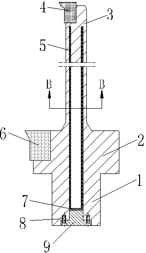
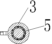
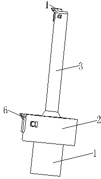
[0015] As attached Figure 1-3 A shock-absorbing boring tool capable of processing slender stepped holes according to the present invention shown includes a clamping part 1, a large boring tool bar 2, a small boring tool bar 3, a small boring tool 4, and a shock-absorbing material 5. Large boring tool 6, sealing ring 7, connecting screw 8, rear cover 9; the rear end of the large boring tool bar 2 is provided with a clamping part 1 for clamping on the machine tool, and a small boring Tool bar 3; the small boring tool 4 is installed on the front end of the small boring tool bar 3, the small boring tool 4 is detachable; the large boring tool 6 is installed on the large boring tool bar 2, the large boring tool 6 is detachable; an annular groove is opened in the cutter bar for filling soft shock-absorbing materials 5 such as polyurethane; the sealing ring 7 is installed at the rear end of the shock...


PUM


Abstract

The invention discloses a shock-absorbing boring cutter capable of machining a slender stepped hole. The shock-absorbing boring cutter comprises a clamping part, a large boring cutter bar, a small boring cutter bar, a small boring cutter, a shock-absorbing material, a large boring cutter, a sealing ring, a connecting bolt and a rear end cover, wherein the clamping part is arranged on the rear end of the large boring cutter bar; the small boring cutter bar is arranged on the front end of the large boring cutter bar; the small boring cutter is arranged on the front end of the small boring cutter bar; the large boring cutter is arranged on the large boring cutter bar; an annular slot is arranged inside the cutter bar for filling the shock-absorbing material; the sealing ring is arranged on the rear end of a shock-absorbing slot for sealing; the rear end cover is fixed by the connecting bolt; the large boring cutter and the small boring cutter can designed to be detachable. According to the scheme of the invention, the shock-absorbing material is arranged inside the cutter bar, so as to prevent shock of the cutter bar from affecting machining precession while a slender hole is machined; two boring cutters are arranged, so that the cutters are not needed to be changed while the stepped hole is machined, thereby avoiding an influence of cutter changing to coaxiality and precision of a workpiece.

Description

Technical field [0001] The invention relates to a tool, in particular to a damping boring tool capable of processing slender stepped holes, and belongs to the technical field of metal cutting tools. Background technique [0002] In mechanical processing, in the processing of stepped holes composed of elongated holes and larger holes with high coaxiality requirements, it is generally used to process the elongated holes first, and then change the tool to process the large holes. This processing method is coaxial It cannot be guaranteed; and when processing slender holes, the tool bar will vibrate because the tool bar is too long, which affects the processing quality of the hole, and the surface of the processed hole is prone to ripples, which cannot reach the surface roughness of the product. It also affects the service life of the tool. In the past, most of the shock absorption methods used were to increase the diameter of the tool bar or reduce the speed and feed rate of the mach...

Claims


Application Information

Patent Timeline
IPC IPC(8): B23B27/00
Inventor 于祥喜
Owner SUZHOU MAIDER MACHINERY
Learn More