Flow front prediction method of non-isothermal resin transfer molding based on mid-plane model

A resin transfer molding and flow front technology, applied in the field of computer numerical simulation, can solve the problems of not considering the coupled heat transfer of the impregnated fiber reinforcement, low precision, and not considering the change in the thickness direction, etc.

Inactive Publication Date: 2012-12-26
SHANGHAI JIAO TONG UNIV
View PDF2 Cites 13 Cited by
  • Summary
  • Abstract
  • Description
  • Claims
  • Application Information

AI Technical Summary

Problems solved by technology

[0006] The purpose of the present invention is to provide a method for predicting the flow front of non-isothermal resin transfer molding based on the mid-surface model, to solve the problem that the numerical simulation method of the non-isothermal RTM process in the prior art adopts the finite difference method in the thickness direction, and only Considering the change of temperature in the thickness direction, the change of other physical quantities (such as velocity, viscosity, curing degree, etc.) The technical problem of low numerical calculation accuracy caused by only using the first-order upwind style in the direction of the mid-surface grid plane

Method used


Image

  • Flow front prediction method of non-isothermal resin transfer molding based on mid-plane model
  • Flow front prediction method of non-isothermal resin transfer molding based on mid-plane model
  • Flow front prediction method of non-isothermal resin transfer molding based on mid-plane model

Examples


Embodiment Construction

[0059] The present invention will be described in detail below in conjunction with the accompanying drawings.

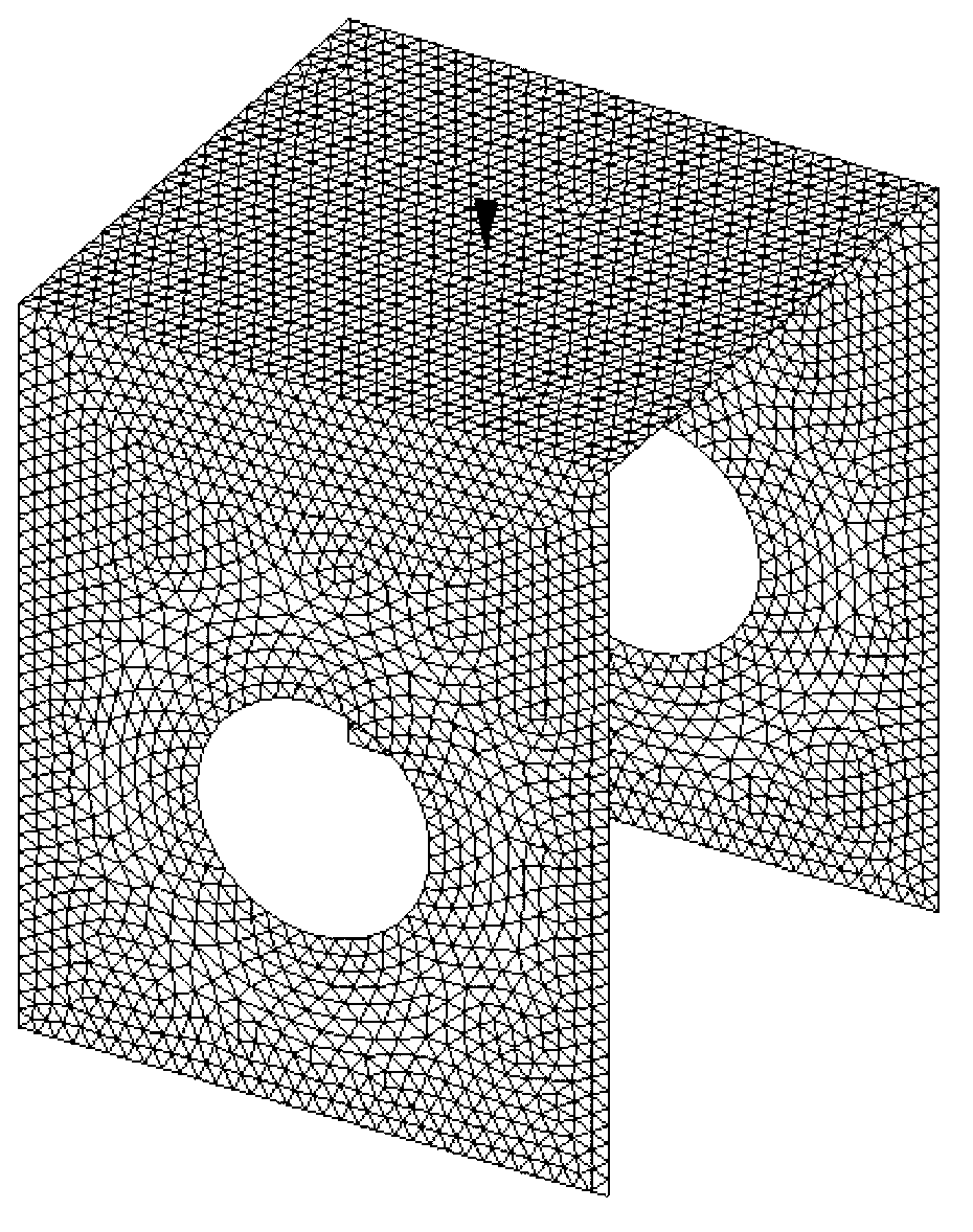
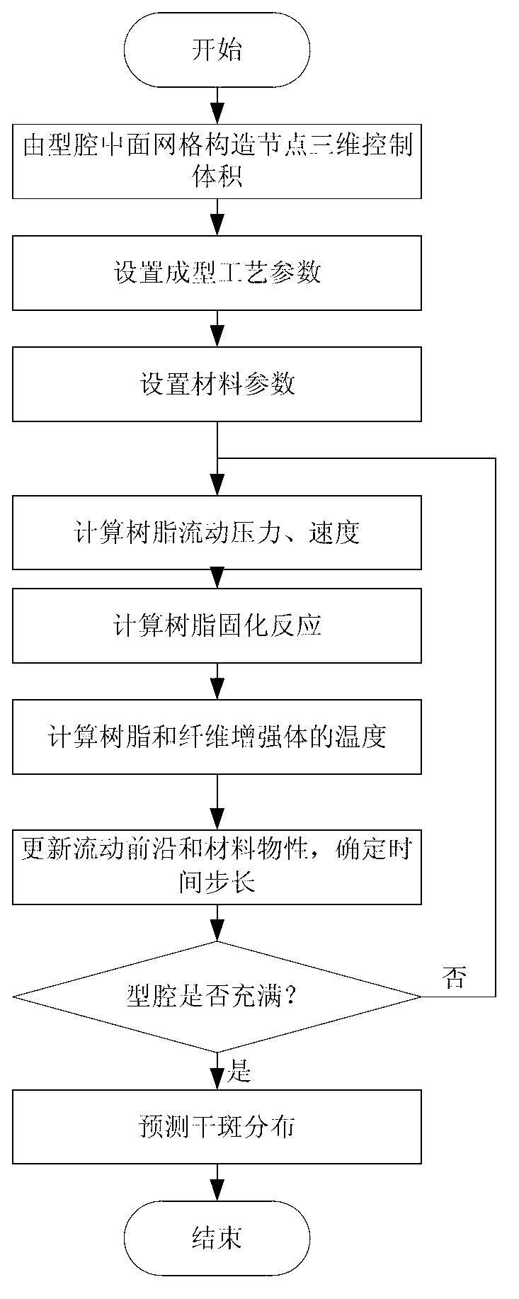
[0060] see figure 1 , which is a schematic diagram of the surface grid and gate position in the geometric model of a product, the thickness of which is 5mm. The steps to predict the flow front are as follows figure 2 As shown, the specific steps are as follows.

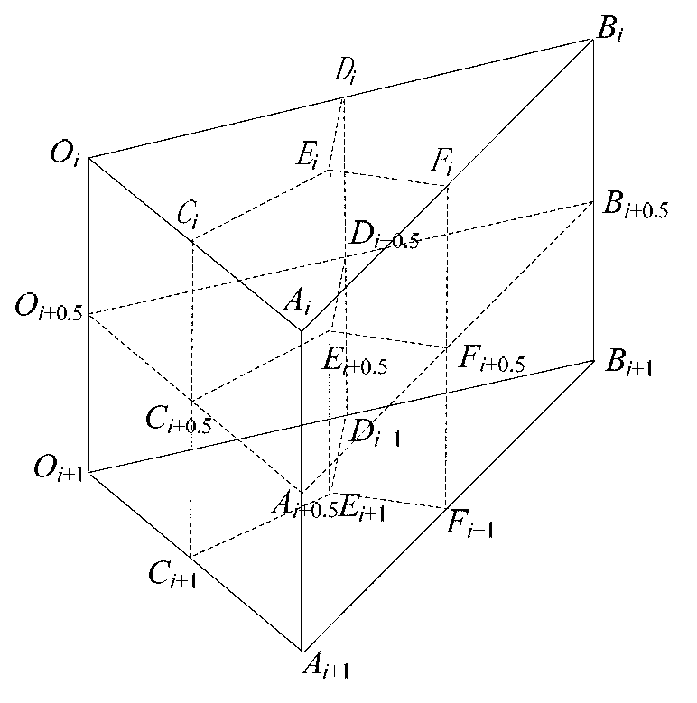
[0061] (1) The volume is controlled in three dimensions by the surface mesh construction nodes in the cavity. see image 3 , the subscripts i and i+1 in the figure (l≥i>0, l is the number of unit layers in the thickness direction of the mid-surface model, l=13 in this example) represent the i and i+1 layer nodes in the thickness direction, connected The corresponding nodes of the i and i+1 layer units are constructed into triangular prism units, and then the sub-control volumes of the nodes are constructed by connecting the body center, face center and edge midpoint of the triangular prism units, and th...


PUM

PropertyMeasurementUnit
porosityaaaaaaaaaa

Abstract

The invention provides a flow front prediction method of non-isothermal resin transfer molding based on a mid-plane model, comprising the following steps: (1) constructing a node three-dimensional control volume by a die cavity mid-plane grid; (2) setting molding technological parameters; (3) setting material parameters; (4) calculating resin flowing pressure and speed; (5) calculating resin solidifying reaction; (6) calculating the temperatures of resin and fiber reinforcements; (7) updating flow front and material physical properties so as to ensure time step; (8) ensuring whether the die cavity is filled, and entering the step (9) if the die cavity has already been filled, or entering the step (5); and (9) predicting the distribution of dry spots. Based on the mid-plane grid, the three-dimensional control volume is constructed and the finite element method of the control volume is used, the changes of viscidity, speed, temperature, curing degree and the like in the thickness direction and the influence to the calculation of pressure field are considered in the calculation, and the flow front of resin transfer molding and the distribution of various physical quantity fields can be predicted more accurately.

Description

technical field [0001] The invention belongs to a computer numerical simulation method, in particular to a method for predicting the flow front of a non-isothermal resin transfer molding based on a mid-plane model, which is used for non-isothermal resin transfer molding of a composite product whose size in the plane direction is much larger than that in the thickness direction forming. Background technique [0002] Resin Transfer Molding (Resin Transfer Molding, RTM) is a process of injecting resin into a closed mold to infiltrate reinforcement materials and solidify them. It is also one of the important methods for producing high-quality fiber-reinforced composite products. Compared with the hot compression molding process, the RTM process has less investment in molding equipment, and the production is green and environmentally friendly. Compared with the traditional hand lay-up process, the RTM product quality is stable and releases less harmful volatile substances, and th...

Claims


Application Information

Patent Timeline
Patent Type & Authority Applications(China)
IPC IPC(8): B29C70/48
Inventor 严波陈军彭雄奇
Owner SHANGHAI JIAO TONG UNIV
Why Eureka
Try Eureka