
Concrete composite slab floorslab with shear key and prefabricated construction and construction method

A technology of shear key and concrete, which is applied in the direction of floors, building structures, building components, etc., can solve the problems of increasing the amount of steel bars, high project cost, and floor thickness, etc., and achieve the effect of reducing the thickness of the plates and the amount of steel bars

Inactive Publication Date: 2012-12-26
SHENYANG JIANZHU UNIVERSITY
View PDF7 Cites 20 Cited by
  • Summary
  • Abstract
  • Description
  • Claims
  • Application Information

AI Technical Summary

Problems solved by technology

Since the prefabricated and cast-in-place parts are connected by steel truss bars, the amount of steel bars is increased. At the same time, in order to ensure the reliable connection of the prefabricated and cast-in-place parts, the steel truss bars used are higher, resulting in thicker floors and higher project costs.

Method used


Image

  • Concrete composite slab floorslab with shear key and prefabricated construction and construction method
  • Concrete composite slab floorslab with shear key and prefabricated construction and construction method
  • Concrete composite slab floorslab with shear key and prefabricated construction and construction method

Examples


Embodiment Construction

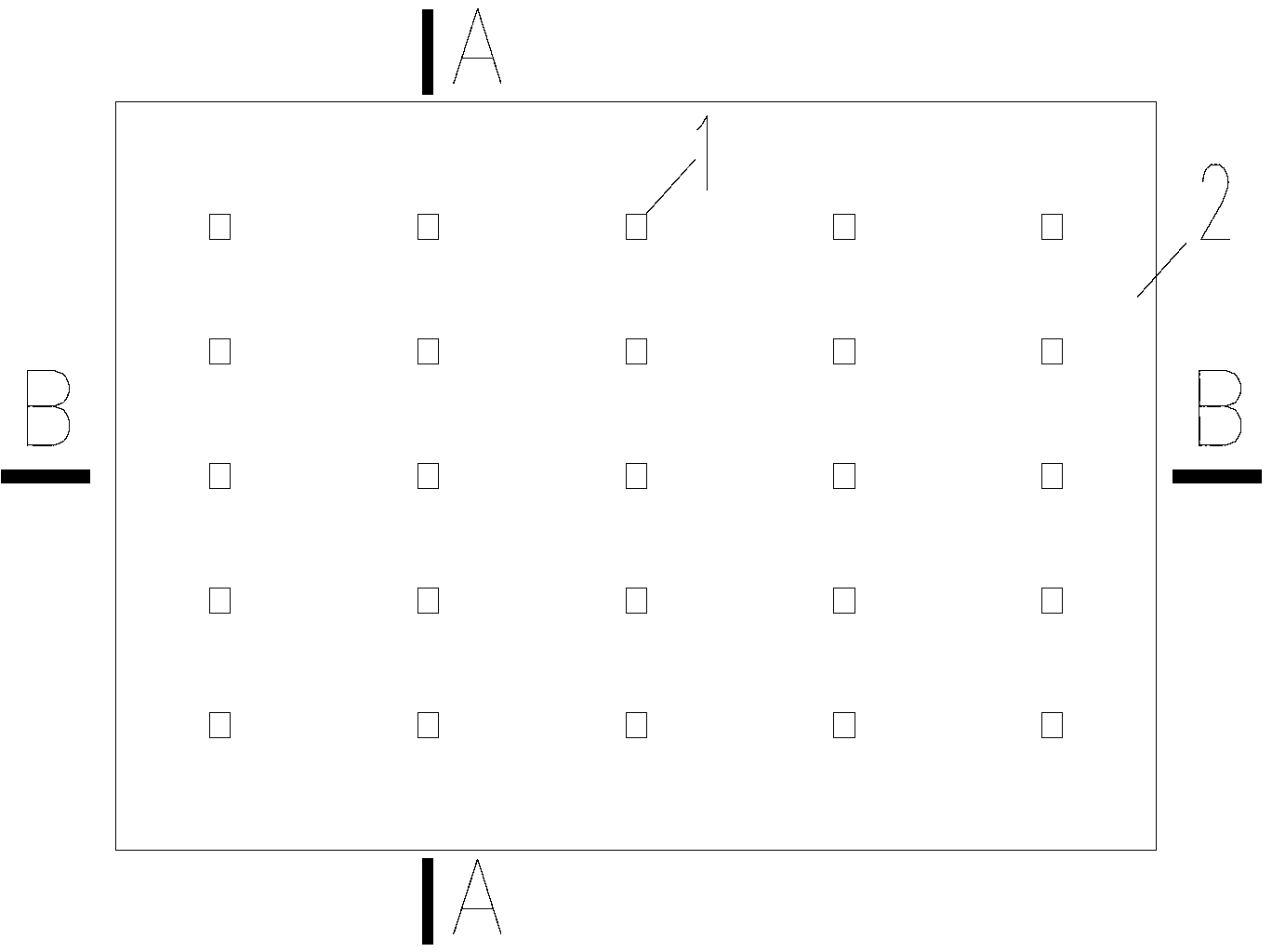
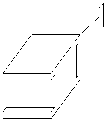
[0034] Such as Figure 1-4 As shown, the present invention is provided with shear keys 1 on the prefabricated bottom plate 2 , and the shear keys 1 are evenly distributed on the prefabricated bottom plate 2 according to the shear force and tensile force that the shear keys 1 need to bear. Among them, the section design of the shear key 1 is I-shaped ( Figure 2-4 ); Alternatively, the shear bond 1 may be in the shape of a ring, a hexagon or other shapes.

[0035] Such as Figure 5-7 As shown, the concrete composite slab floor slab with shear key of the present invention mainly includes the cast-in-place layer 3 and the prefabricated base plate 2 arranged up and down, the prefabricated base plate 2 is provided with the shear key 1, and the prefabricated base plate 2 is connected to the existing base plate through the shear key 1. The pouring layers 3 are connected to form a firm bonded structure. One end of the shear key 1 is buried in the prefabricated bottom plate, and the...


PUM


Abstract

The invention relates to the field of fabricated type concrete buildings, in particular to a concrete composite slab floorslab with a shear key, a prefabricated construction and a construction method. The produced concrete composite slab floorslab can be used as a floorslab applied in the fabricated type concrete buildings. The concrete composite slab floorslab is composed of a prefabricated reinforced concrete base plate, a prefabricated concrete shear key and a cast-in-place reinforced concrete layer. The section of the prefabricated concrete shear key is designed to be in a lying-H shape, or a ring shape, or a hexagon shape or other shapes which can play a role in shearing resistance. One end of the prefabricated concrete shear key is embedded in the prefabricated reinforced concrete base plate, and the other end of the prefabricated concrete shear key is embedded in the cast-in-place reinforced concrete layer. When the cast-in-place reinforced concrete layer is made, concrete is poured to the top portion or above the top portion of the shear key. The shear key is used to connect the prefabricated reinforced concrete base plate and the cast-in-place reinforced concrete layer to form the whole floorslab, and the prefabricated concrete shear key is used to bear a shearing force and a tensile force between the prefabricated reinforced concrete base plate and the cast-in-place reinforced concrete layer. By means of the concrete composite slab floorslab with the shear key, using amount of steel bars used to connect the prefabricated reinforced concrete base plate and the cast-in-place reinforced concrete layer can be effectively reduced, and thickness of the concrete composite slab floorslab is reduced.

Description

technical field [0001] The invention relates to the field of prefabricated concrete buildings, in particular to a concrete laminated slab floor with shear keys, a prefabricated structure and a construction method. The produced concrete laminated slab floor can be used as a floor slab used in prefabricated concrete buildings. Background technique [0002] At present, in the actual prefabricated concrete buildings, self-supporting reinforced truss concrete composite slabs are commonly used in floor slabs. This composite slab is composed of a prefabricated reinforced concrete floor (hereinafter referred to as the prefabricated floor) and a cast-in-place reinforced concrete layer (hereinafter referred to as the cast-in-place layer). Thin steel truss, which connects the upper and lower steel bars of the concrete floor, bears the shear force and the pull force that make the prefabricated floor and the cast-in-place layer shift from each other. Since the prefabricated and cast-in-...

Claims


Application Information

Patent Timeline
IPC IPC(8): E04B5/23E04G21/02
Inventor 李明赵唯坚孙哲哲
Owner SHENYANG JIANZHU UNIVERSITY
Learn More