
Isothermal-isobaric compressed air energy storage system

A technology of compressed air energy storage and equal pressure, which is applied in the direction of steam engine devices, machines/engines, mechanical equipment, etc. It can solve the problems of not meeting the requirements of green energy development and the impact of system efficiency, and achieve an unlimited and broad energy storage period. Use prospects, the effect of improving system efficiency

Active Publication Date: 2012-12-26
INST OF ENGINEERING THERMOPHYSICS - CHINESE ACAD OF SCI
View PDF9 Cites 34 Cited by
  • Summary
  • Abstract
  • Description
  • Claims
  • Application Information

AI Technical Summary

Problems solved by technology

The traditional compressed air energy storage system has the advantages of large energy storage capacity, long energy storage period, high efficiency and relatively small unit investment; however, the traditional compressed air energy storage system still relies on burning fossil fuels to provide heat sources. The threat of gradual depletion and rising prices, on the other hand, its combustion still produces pollutants such as nitrogen oxides and greenhouse gases, which does not meet the requirements of green energy development; what is more fatal is that traditional compressed air energy storage systems also require specific geographical conditions Build large gas storage chambers, such as rock caverns, salt caverns, abandoned mine shafts, etc.; and as the gas is inflated and deflated, the pressure and temperature of the compressed air will change, so the efficiency of the system will also be affected
In addition, large cavernous gas storage chambers of compressed air energy storage systems will be affected by geological disasters such as earthquakes

Method used


Image

  • Isothermal-isobaric compressed air energy storage system
  • Isothermal-isobaric compressed air energy storage system
  • Isothermal-isobaric compressed air energy storage system

Examples


Embodiment

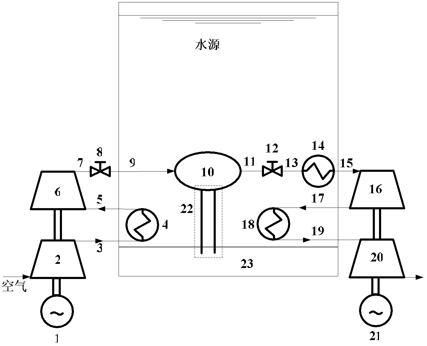
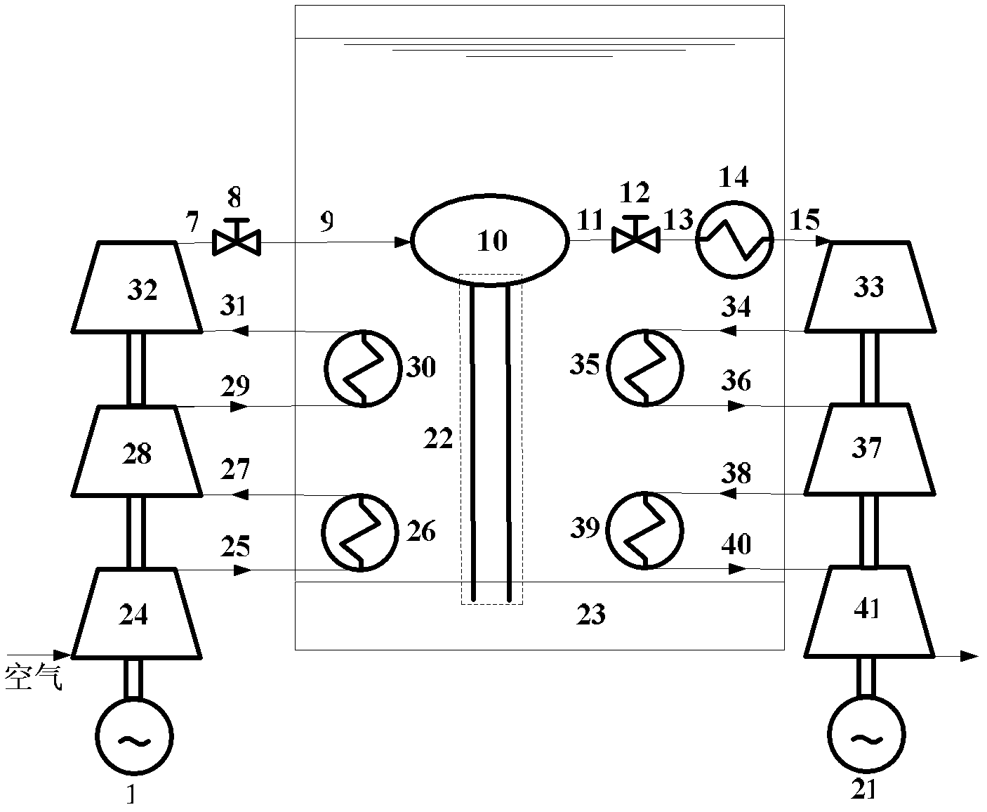
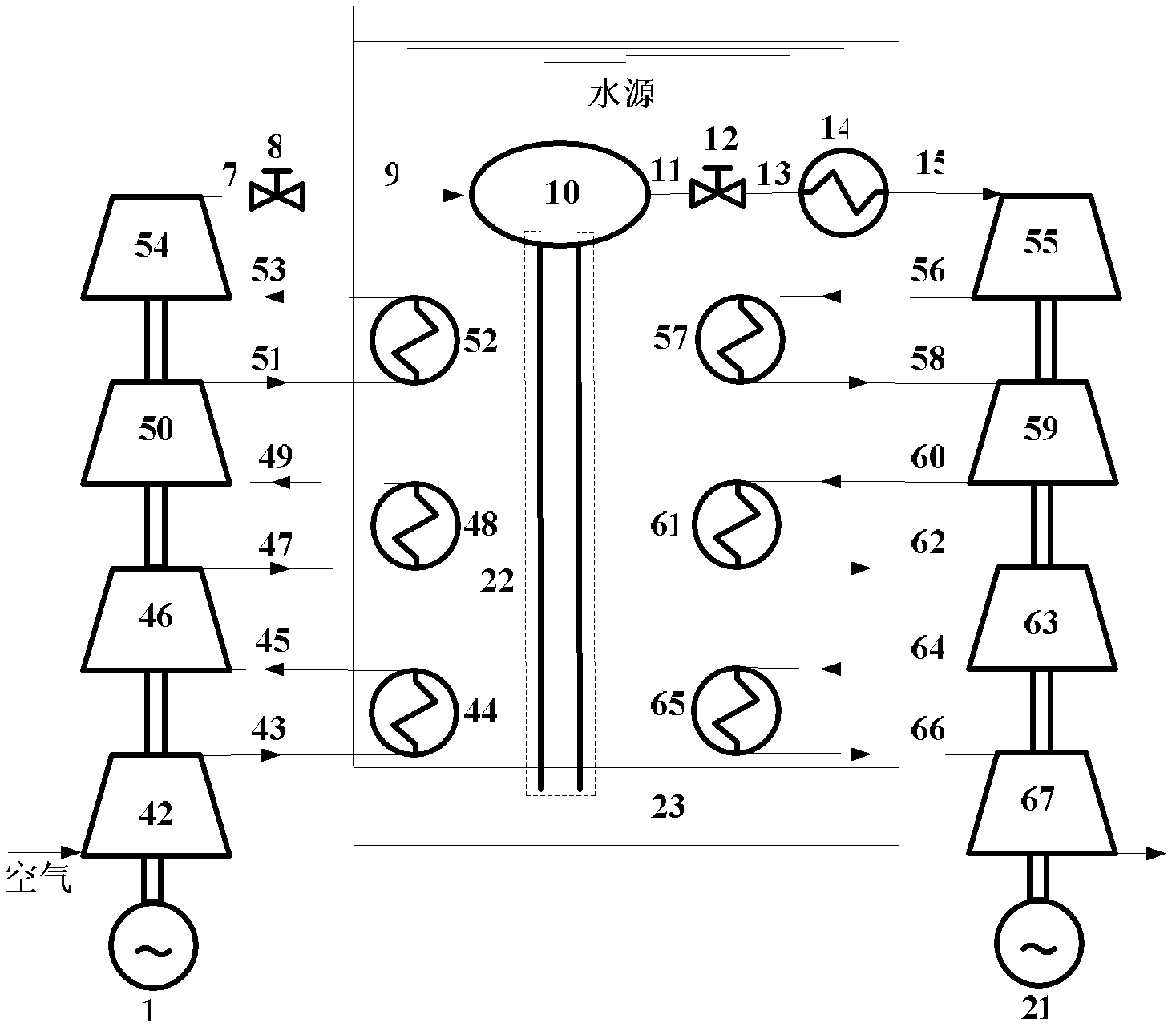
[0039] figure 1 Shown is the embodiment 1 of the isothermal and isobaric compressed air energy storage system of the present invention, which adopts two-stage compression, interstage cooling and two-stage expansion, interstage heating. Among them, motor 1, low-pressure compressor 2, high-pressure compressor 6, high-pressure expander 16, low-pressure expander 20, heat exchangers 4, 14, 18, valves 8, 12, pipelines 3, 5, 7, 9, 11, 13, 15, 17, 19, flexible gas storage device 10, generator 21, fixture 22, underwater lithosphere 23, air and water sources.

[0040]The electric motor 1 is fixedly connected to the common transmission shaft of the compressor unit, and the generator 21 is fixedly connected to the common transmission shaft of the expansion unit. The low-pressure compressor 2 is connected to the heat exchanger 4 through the pipeline 3 and the high-pressure compressor 6 through the pipeline 5; the high-pressure compressor 6 is connected to the flexible gas storage device 1...


PUM


Abstract

The invention discloses an isothermal-isobaric compressed air energy storage system, and relates to an energy storage technology. Through the adoption of the system, air is compressed into an underwater flexible air storage device by an air compressor at valley of power demand, so that electric energy is converted into internal energy of the air to be stored; and after the heat of high pressure air is absorbed by a heat exchanger, the high pressure air in the air storage device drives a power generator to generate power by an expansion machine at peak of power demand. Through the adoption of the isothermal-isobaric compressed air energy storage system disclosed by the invention, a constant pressure is kept within the air storage device by means of underwater pressure, and approximately isothermal compression and expansion process is achieved by using an interstate cooling and heating measure; therefore, the efficiency of the system is increased. Meanwhile, the isothermal-isobaric compressed air energy storage system disclosed by the invention has the advantages of no limitation from energy storage period, environment friendliness, wide use prospect, and so on, and is suitable for power supplies with various types; and the air storage device is uneasy to be affected by geological disasters such as earthquake and the like.

Description

technical field [0001] The invention relates to the technical field of energy storage, in particular to an isothermal and isobaric compressed air energy storage system. Background technique [0002] For a long time, in order to meet the ever-increasing power load requirements, the power sector has to build power generation capacity according to the maximum load requirements. On the one hand, this has caused a large amount of surplus and waste of power generation capacity; on the other hand, the power sector has to limit power consumption during peak hours. Therefore, there is an urgent need for an economical, stable, reliable, and efficient power storage system to match it and improve the situation of excessive peak-to-valley load differences in the system. Especially for nuclear power plants and other power systems that can only operate at high levels, the demand for power energy storage systems is even more urgent. More importantly, the electric energy storage system is ...

Claims


Application Information

Patent Timeline
IPC IPC(8): F01D15/10F01K3/08
Inventor 陈海生严晓辉张雪辉孟爱红谭春青
Owner INST OF ENGINEERING THERMOPHYSICS - CHINESE ACAD OF SCI
Learn More