Hot and cold water supply device

A water supply device, cold and hot water technology, applied in hot water central heating systems, residential hot water supply systems, refrigerators, etc., can solve the problems of reduced energy utilization efficiency and heating time, so as to improve energy efficiency and shorten heating time, the effect of shortening the heat storage standby time

Active Publication Date: 2015-11-18
PANASONIC CORP
View PDF7 Cites 0 Cited by
  • Summary
  • Abstract
  • Description
  • Claims
  • Application Information

AI Technical Summary

Problems solved by technology

Moreover, since the thermal storage tank 300 after the temperature has dropped is heated by the heat pump, it takes time for heating, and the energy utilization efficiency decreases.

Method used


Image

  • Hot and cold water supply device
  • Hot and cold water supply device
  • Hot and cold water supply device

Examples


Embodiment approach 1

[0055] use Figure 1~Figure 4 The hot and cold water supply device according to Embodiment 1 of the present invention will be described.

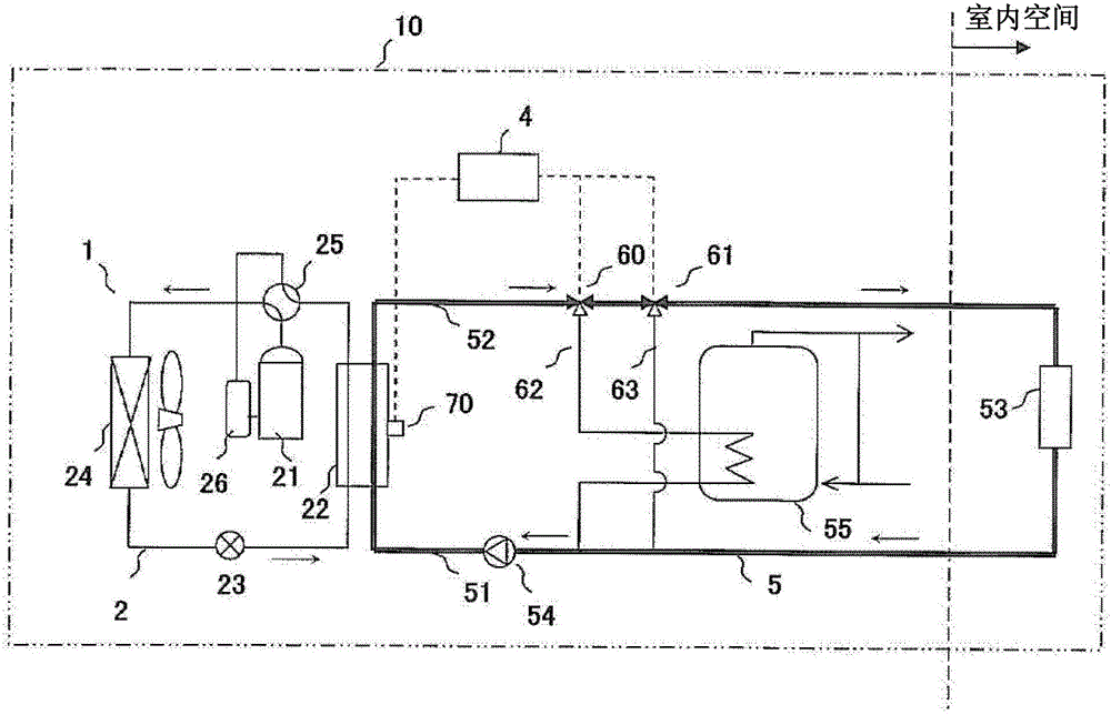
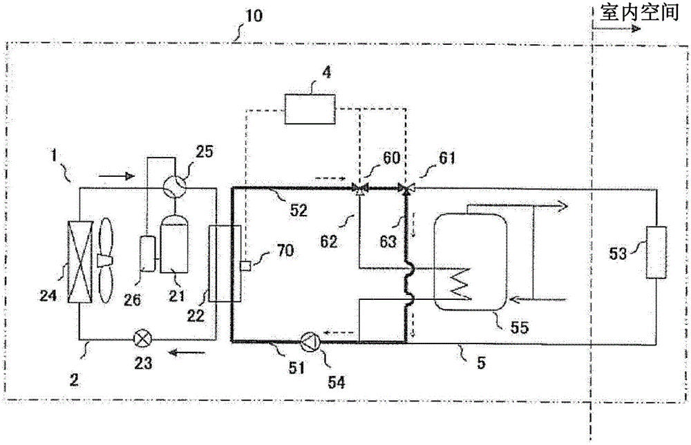
[0056] Figure 1~Figure 3 It is a schematic configuration diagram of the cold and hot water supply apparatus of this embodiment, figure 1 is a schematic configuration diagram showing the flow of fluid in the cooling operation mode, figure 2 is a schematic configuration diagram showing the flow of fluid when switching from the cooling operation mode to the heat storage operation mode, image 3 is a schematic configuration diagram showing the flow of fluid in the thermal storage operation mode, Figure 4 It is a flow chart of the operation of the hot and cold water supply device of the present embodiment.

[0057] use figure 1 The first hot and cold water supply device according to Embodiment 1 of the present invention will be described.

[0058] The hot and cold water supply device 10 includes a refrigeration cycle device 1 , a fluid ...

Embodiment approach 2

[0103] Figure 5 Shown is the cold and hot water heater of Embodiment 2 of the present invention. In addition, in this embodiment, the same components as those in Embodiment 1 are assigned the same reference numerals, and descriptions thereof are omitted.

[0104] In this embodiment, the basic configuration is also the same as that of Embodiment 1, but a heat storage tank temperature sensor 71 is provided. That is, in order to set the predetermined temperature To in Embodiment 1, the heat storage tank temperature sensor 71 is provided.

[0105] With the installation of the heat storage tank temperature sensor 71 described above, the predetermined temperature To is set to a temperature equal to the detected temperature Tt of the heat storage tank temperature sensor 71 provided in the heat storage tank 55 . However, the predetermined temperature To may be set several degrees lower or higher than the temperature Tt detected by the heat storage tank temperature sensor 71 .

[0...


PUM


Abstract

According to a cold / hot water supply apparatus of the present invention, when a cooling operation mode in which fluid which flows out from a first heat exchanger 22 absorbs heat in a third heat exchanger 53 is switched to a heat-accumulation operation mode in which fluid which flows out from a first heat exchanger 22 heats water in a heat accumulator tank 55, it is determined whether fluid which flows out from the first heat exchanger 22 should be made to flow to the heat accumulator tank 55 or to return to the first heat exchanger 22 without through the heat accumulator tank 55. According to this configuration, heating time of the heat accumulator tank 55 can be shortened, and energy efficiency can be enhanced.

Description

technical field [0001] The present invention relates to a hot and cold water supply device that uses a heat pump to store heat in cooling and heating equipment and heat storage tanks in indoor spaces. Background technique [0002] Conventionally, there is known a hot and cold water supply device including a cooling operation mode for cooling an indoor space and a heat storage operation mode for heating a heat storage tank (for example, refer to Patent Document 1). [0003] Figure 6 Shown is a refrigeration cycle device 100 for cooling and heating an indoor space and storing heat in a heat storage tank 300 . In the refrigeration cycle device 100, the refrigerant circuit 110 for circulating the refrigerant, the compressor 111, the four-way valve 112, the first heat exchanger 113, the expansion member 114, and the air-to-fluid heat exchanger 115 are connected in a ring shape by piping. . [0004] The first heat exchanger 113 includes a refrigerant circuit 110 and a fluid cir...

Claims


Application Information

Patent Timeline
Patent Type & Authority Patents(China)
IPC IPC(8): F25B29/00F25B49/02
CPCF24D11/0214F24D3/18F24D17/02F24D19/1039F24F3/06F24F5/0096F24F2203/021Y02B30/12Y02B30/126
Inventor 谏山安彦青山繁男
Owner PANASONIC CORP
Why Eureka
Try Eureka