Automatic microfluid sample introduction device capable of realizing unpowered sequential sample introduction and application thereof

An automatic sampling and microfluidic technology, applied in the direction of analyzing materials, instruments, etc., can solve the problems of large size, complicated operation, complicated design, etc., and achieve the effect of small size, small dead volume, and easy production.

Active Publication Date: 2014-06-04
ZHEJIANG UNIV
View PDF3 Cites 0 Cited by
  • Summary
  • Abstract
  • Description
  • Claims
  • Application Information

AI Technical Summary

Problems solved by technology

However, the current automatic sampling device is complex in design and relatively large in size
Although its technology is relatively mature, it has disadvantages such as complex operation, expensive equipment, and large dead volume. Therefore, one of the current research trends in automatic sampling is to develop towards miniaturization and chip development.

Method used


Image

  • Automatic microfluid sample introduction device capable of realizing unpowered sequential sample introduction and application thereof
  • Automatic microfluid sample introduction device capable of realizing unpowered sequential sample introduction and application thereof
  • Automatic microfluid sample introduction device capable of realizing unpowered sequential sample introduction and application thereof

Examples


Embodiment 1

[0022] Example 1 A microfluidic automatic sampling device for unpowered sequential sampling

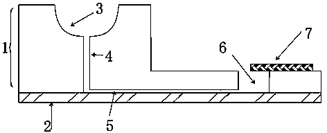
[0023] see figure 1 , the device of the present invention is composed of a microfluidic layer 1 and a bottom cover sheet layer 2, a U-shaped liquid storage tank 3, a sample injection channel 4, a microfluidic channel 5, a sample outlet 6, and a waste liquid removal module 7. The sample outlet 6 By being a cylindrical notch, the microfluidic channel 5 is connected to the sample inlet channel 4 and the sample outlet 6, the waste liquid removal module 7 is covered on the sample outlet 6, and its front edge is in the middle of the sample outlet 6, and the microfluidic Layer 1 and bottom cover sheet layer 2 are sealed together, and the microfluidic layer 1 contains at least one of the above-described sampling units.

[0024] The materials of the waste liquid removal module 6 are sponge and filter paper.

[0025] The curvature of the bottom of the U-shaped liquid storage tank should be ge...

Embodiment 2

[0029] Example 2 Using the device of the present invention

[0030] see figure 1 , a single-channel injection example

[0031] The bottom cover sheet layer 2 is a glass surface coated with a nano-gold film, and the gold film is a smooth surface without any modification on the surface. The microfluidic layer 1 is sealed with the nano-gold film layer by means of surface plasma treatment, solid glue bonding, etc. If the microfluidic layer 1 is a flexible polymer, gently squeeze the microfluidic layer 1 Sealing is also possible. The signal after the sample solution enters the microfluidic channel 5 is recorded by the surface plasmon resonance device.

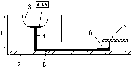
[0032] The first step is to fill the bottom of the U-shaped liquid storage tank 3, the sample injection channel 4, the microfluidic channel 5, and the bottom of the sample outlet 6 with buffer. The process is as follows: figure 2 shown. An appropriate amount of buffer is placed in the U-shaped liquid storage tank 3, and a posi...


PUM

PropertyMeasurementUnit
diameteraaaaaaaaaa

Abstract

The invention provides an automatic microfluid sample introduction device capable of realizing unpowered sequential sample introduction. The device comprises a microfluid layer, a bottom cover plate layer, a U-shaped liquid storage groove, a sample introduction channel, a microfluid channel, a sample outlet and a waste liquor removal module covered on the sample outlet, wherein the microfluid layer and the bottom cover plate layer are sealed together; and the microfluid layer contains at least one sample introduction unit. The device provided by the invention has the advantages of controllable sample introduction speed, automation, continuity and convenience in operation, can realize the sequential sample introduction of various sample solutions, also has the advantages of reasonable design, simplicity and convenience in manufacturing, small size, wide sample introduction quantity range and small dead volume, and realizes sequential sample introduction. Therefore, the device provided by the invention, actually a novel microfluid chip device, is suitable for fluid analysis and detection.

Description

technical field [0001] The invention belongs to a biotechnology detection device, and relates to a microfluidic automatic sampling device without power sequential sampling, which can be applied in fluid analysis and detection. Background technique [0002] In the field of biomedicine, fluid analysis and detection play an important role. The highly automated sampling system can realize the online analysis of liquid quantitative and constant speed. However, the current automatic sampling device is complicated in design and relatively large in size. Although its technology is relatively mature, it has disadvantages such as complicated operation, expensive equipment, and large dead volume. Therefore, one of the current research trends of automatic sample injection is to develop towards miniaturization and chipization. The unpowered sampling chip can completely get rid of the shackles of external equipment, and at the same time achieve relatively stable and precise liquid contr...

Claims


Application Information

Patent Timeline
Patent Type & Authority Patents(China)
IPC IPC(8): G01N35/10
Inventor 牟颖解飞杨梦朝周超金伟金钦汉
Owner ZHEJIANG UNIV
Why Eureka
Try Eureka