Buffer device and buffer method for feeding back shared light based on FDL (fiber delay line) loop

An optical cache and cache technology, applied in the field of optical fiber communication, can solve the problems of bulky size, low utilization rate of FDL, complex cache control method, etc., and achieve the effect of reducing high load

Inactive Publication Date: 2012-12-26
CHONGQING UNIV OF POSTS & TELECOMM
View PDF3 Cites 12 Cited by
  • Summary
  • Abstract
  • Description
  • Claims
  • Application Information

AI Technical Summary

Problems solved by technology

[0004] Aiming at the problem that the existing Optical Packet Switching OPS node is configured with fiber delay line FDL cache to solve the problem of large volume in packet competition, the discrete cache granularity of FDL makes its utilization rate not high, and the cache control method is complicated, the present invention designs a FDL ring-based Feedback shared optical buffer device and control method

Method used


Image

  • Buffer device and buffer method for feeding back shared light based on FDL (fiber delay line) loop
  • Buffer device and buffer method for feeding back shared light based on FDL (fiber delay line) loop
  • Buffer device and buffer method for feeding back shared light based on FDL (fiber delay line) loop

Examples


Embodiment Construction

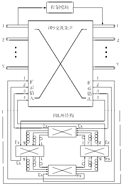
[0014] The core node of the OPS network includes an OPS switching matrix, a control module, and an FDL ring buffer device. The OPS switching matrix includes N basic input / output ports and 4 extended input / output ports. The basic input port of the OPS switching matrix amplifies and regenerates packets from the same optical fiber channel, separates the packet header and payload, extracts packet header information to the control module, and performs routing addressing and control scheduling. The control module is responsible for Process packet header information and issue all instructions, and configure the cross-connection of basic input and basic output ports of the OPS switching matrix. The OPS switching matrix completes the cross-connection function of the payload according to the instructions of the control module. The FDL ring buffer device buffers the conflicting packets of the failure of the wavelength channel of the same output port of the OPS switching matrix, and throu...


PUM


Abstract

The invention provides a buffer device and a buffer method for feeding back shared light based on an FDL (fiber delay line) loop, and relates to the technical field of optical fiber communication. The FDL loop comprises four sub switching matrixes and four FDL buffer groups; a conflicting optical packet can go into an extended input port of the FDL loop from any extended output port of an OPS (optical packet switching) node when the optical packet of the optical OPS node encounters an obstruction; an available FDL can be selected in the FDL loop to buffer the optical packet until the output port of the OPS node is free, and the conflicting optical packet departs from the FDL loop through the extended output port of the FDL buffer group, and is switched into the free output port of the OPS through an OPS matrix. The device allows the conflicting optical packet to go into and depart from the FDL loop through the extended input / output port of the FDL loop; the structure of feeding back connection allows the optical packet to pass through the FDL buffer group for a plurality of times; the success probability of buffering the conflicting optical packet is improved, and the utilization rate of the FDL loop is improved. The problems of port contention of the optical packet switching network and utilization rate of finite number of FDLs are well solved.

Description

technical field [0001] The invention relates to the field of optical fiber communication, in particular to an optical buffer device used for the core node of optical packet switching. technical background [0002] Optical packet switching (OPS: Optical packet switching) is a new type of optical domain switching technology that has emerged in recent years. It combines the advantages of electronic packet and optical switching, and supports flexible, arbitrary small-grained packet-level optical domain switching. It is considered by the industry to be the It is the most ideal switching method to solve the bottleneck problem of network optical / electrical / optical information conversion in the future. In the OPS network, when multiple packets of the same wavelength need to be output from the same port of the intermediate node at the same time, port competition will occur. However, in the Internet network dominated by IP services, the packet burst is very large, and the traffic in O...

Claims


Application Information

Patent Timeline
Patent Type & Authority Applications(China)
IPC IPC(8): H04L12/56H04Q11/00
Inventor 刘焕淋庞俊宇方强江上王杨杨王寅
Owner CHONGQING UNIV OF POSTS & TELECOMM
Why Eureka
Try Eureka