Air-cooled blow needle mechanism

An air-cooled needle body technology, which is applied in the field of air-cooled needle blowing mechanism and plastic hollow container, to achieve the effect of improving heat dissipation, improving production efficiency and shortening inflation time

Active Publication Date: 2014-06-18
SUZHOU TONGDA MACHINERY
View PDF5 Cites 7 Cited by
  • Summary
  • Abstract
  • Description
  • Claims
  • Application Information

AI Technical Summary

Problems solved by technology

However, due to the actual use process, the cooling water entering the blowing needle cavity is very easy to seep from the matching position between the blowing needle 2 and the blowing needle body 1 and from the matching position between the blowing tube 3 and the blowing needle 2. out, resulting in the technical problem mentioned above by the applicant
In addition, since water is used as the cooling medium only to cool the blowing needle 2, it is not enough to accelerate the blowing speed of the parison, because water is impossible and absolutely not allowed to participate in the blowing of the parison; The structure of the needle 2 is unreasonable, thus affecting the cooling speed and cooling effect
[0005] The applicant has searched the literature, but there is rare technical information about the needle blowing mechanism in the published Chinese patent literature, but it is recommended by the authorized announcement number CN201776905U "Blowing needle cooling circulation device of blow molding machine", however, since the cooling medium used in this patent solution is water, it has no reference significance for making up for the applicant's above-mentioned technical problems

Method used


Image

  • Air-cooled blow needle mechanism
  • Air-cooled blow needle mechanism
  • Air-cooled blow needle mechanism

Examples


Embodiment

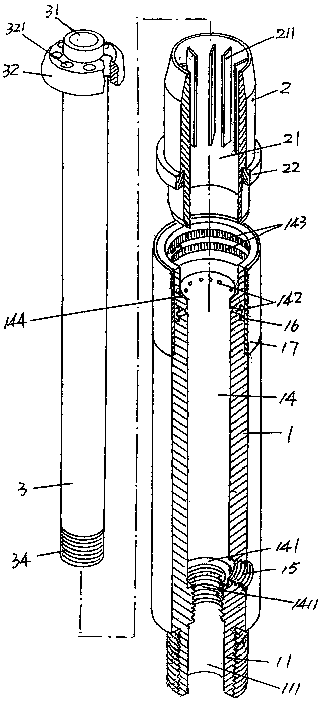
[0016] See figure 1 , a blowing needle body 1 whose material is metal and preferably stainless steel is provided, the blowing needle body 1 is hollow, more specifically, the blowing needle body 1 is formed with a hollow cavity 14 penetrating from one end to the other end, At one end of the blowing needle body 1 that is figure 1 The lower end shown is extended with an inlet pipe fitting 11 , and a cooling air inlet 15 is opened on the side of the end, and the cooling air inlet 15 communicates with the aforementioned hollow cavity 14 . In the state of use, the aforesaid inlet pipe fitting 11 is connected with an air source pipeline providing an air source device, such as an air compressor or an air pump. In the hollow cavity 14 and toward one end of the air inlet pipe fitting 11 is formed a blowing pipe fitting seat 141 with an internal thread 1411 , and the cooling air inlet 15 is located above the blowing pipe fitting seat 141 . At the other end of the blowing needle bo...


PUM


Abstract

The invention relates to an air-cooled blow needle mechanism, and belongs to the technical field of an air blowing mechanism of a blowing machine. The mechanism comprises a blow needle body with a hollow chamber. An air inlet pipe joint extends at one end of the blow needle body. A cooling air inlet is provided on a side of the blow needle body. A blowing pipe joint seat is formed on a wall of the hollow chamber. An annular air groove is provided on the other end of the blow needle body, and a cooling sleeve is fixed. A set of cooling sleeve cooling air ports is provided on the inner wall of the hollow chamber. A blow needle head with a blow needle head cavity is formed. A set of heat sinks is formed on the inner wall of the blow needle head cavity. The blowing pipe is positioned in the hollow chamber. One end of the blowing pipe extends out of the blow needle head, and a blow needle cap is formed. A set of secondary air jet holes is provided on the blow needle cap. The space between the outer wall of the lowing pipe and the inner wall of the hollow chamber forms a cooling air entraining cavity. The cooling air inlet communicates with the cooling air entraining cavity. The cooling sleeve cooling air ports communicate with the cooling air entraining cavity. The mechanism has the advantages that: with the mechanism, product is prevented from being polluted; blank blowing time is shortened; production efficiency is improved; and heat dissipation effect is improved.

Description

technical field [0001] The invention belongs to the technical field of air blowing devices for blow molding machines, and in particular relates to an air-cooled needle blowing mechanism, which is used to blow air into a parison of a plastic hollow container in a mold, so that the parison is inflated and formed, and the mold is opened Finally, the finished plastic hollow container is obtained. Background technique [0002] The blowing needle needs to be cooled during the working process. The purpose of cooling is to form a significant temperature difference between the blowing needle and the plastic hollow container. Otherwise, when the blowing needle withdraws from the plastic hollow container, it will stick to the mouth of the plastic hollow container. , affecting the quality of plastic hollow containers. [0003] Since water is commonly used to cool the blowing needles in the prior art, the industry customarily refers to such blowing needles as water-cooled blowing needle...

Claims


Application Information

Patent Timeline
Patent Type & Authority Patents(China)
IPC IPC(8): B29C49/60B29L22/00
Inventor 任慎宏吴国春
Owner SUZHOU TONGDA MACHINERY
Why Eureka
Try Eureka