A backup emergency braking system for automobiles

A brake system, emergency technology, applied in the direction of vehicle components, brakes, brake components, etc., can solve the problems of road or vehicle damage, non-reusable, poor safety, etc., to prolong the service life, prevent breakage, and good braking effect Effect

Inactive Publication Date: 2014-10-15
HENAN UNIV OF SCI & TECH
View PDF6 Cites 2 Cited by
  • Summary
  • Abstract
  • Description
  • Claims
  • Application Information

AI Technical Summary

Problems solved by technology

[0007] In order to solve the problems of poor safety, easy damage to roads or vehicles, and inability to reuse the emergency braking system in the prior art, the present invention provides a backup emergency braking system for automobiles.

Method used


Image

  • A backup emergency braking system for automobiles
  • A backup emergency braking system for automobiles
  • A backup emergency braking system for automobiles

Examples


Embodiment 1

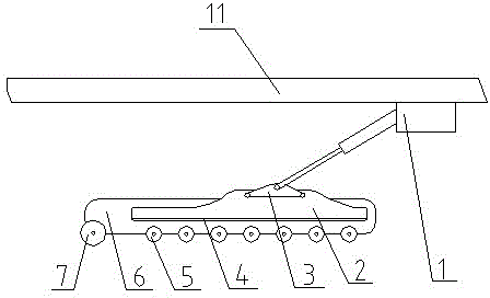
[0024] Such as figure 1 As shown, a spare emergency braking system for automobiles is mainly composed of an oil cylinder 1 and a brake box 6, the bottom of the brake box 6 is provided with a buffer roller 7 and multiple sets of brake rollers 5, the brake roller 5 and the buffer roller 7 They are all arranged perpendicular to the direction of travel, and the buffer roller 7 is arranged at the front end position of the bottom of the brake box 6, the brake box 6 is provided with a pressure seat 2, the bottom of the pressure seat 2 is provided with a friction plate 4, and the friction plate 4 There is a gap between it and the brake roller 5. There is a push block 3 on the top of the pressure seat 2. The upper end of the push block 3 is hinged to the piston rod of the oil cylinder 1 arranged at the bottom of the vehicle beam 11. The piston rod of the oil cylinder 1 is tilted towards the front of the vehicle. , and the angle formed by the piston rod and the vehicle beam 11 is 5-65°....

Embodiment 2

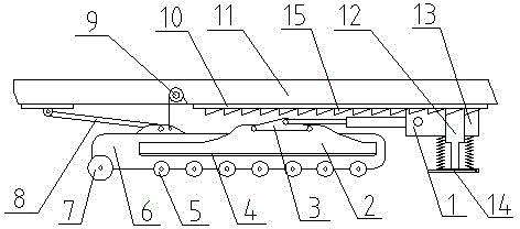
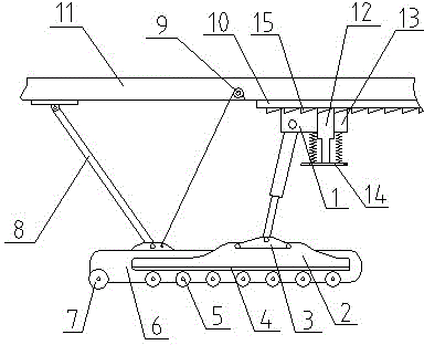
[0026] Such as figure 2 As shown, a spare emergency braking system for automobiles is mainly composed of an oil cylinder 1 and a brake box 6. The bottom of the brake box 6 is provided with a buffer roller 7 and multiple groups of brake rollers 5, and the buffer roller 7 is arranged on the brake At the front end position of the bottom of the casing 6, the brake casing 6 is provided with a pressure seat 2, and the bottom of the pressure seat 2 is provided with a friction plate 4, and there is a gap between the friction plate 4 and the brake roller 5, and the top of the pressure seat 2 A push block 3 is provided, the upper end of the push block 3 is hinged to the piston rod of the oil cylinder 1, the piston rod of the oil cylinder 1 tilts towards the front of the vehicle, and the angle formed by the piston rod and the vehicle beam 11 is 5-65°;

[0027] The bottom of the vehicle beam 11 is provided with a slideway 10, and a slide block 13 is clamped in the slideway 10, and the oi...


PUM


Abstract

The invention provides a reserved emergency braking system of an automobile, which is formed by an oil cylinder and a brake tank body, wherein a buffering roller and a plurality of groups of brake rollers are arranged at the bottom of the brake tank body; the buffering roller is arranged at the front end of the bottom of the brake tank body; the brake tank body is internally provided with a pressure bearing seat and a friction sheet is arranged at the bottom of the pressure bearing seat; a gap is reserved between the friction sheet and the brake rollers; the top of the pressure bearing seat is hinged with a piston rod of the oil cylinder arranged at the bottom of an automobile beam; and the piston rod of the oil cylinder is obliquely placed towards the front side of the automobile. The brake rollers are used for braking and the braking is carried out on rolling bodies; the abrasion caused on a road surface and the automobile is small; meanwhile, the brake rollers are more so that the total grounding area is larger than the grounding area of wheels of the automobile and the braking effect is good; and meanwhile, the brake tank body has a certain length so that the distribution of the brake rollers is a rectangular frame, the brake has the better guiding performance, and the brake is safer.

Description

technical field [0001] The invention relates to a braking system in the field of machinery, in particular to a spare emergency braking system for automobiles. Background technique [0002] In passenger and freight transportation, the performance of the brake system of the car is directly related to the safety of human life and property. There are countless accidents directly caused by the failure of the brake system of the car, especially on the long downhill section of the mountain road, due to fatigue driving or improper operation of the driver (If you don't go to the cooling pool to cool the brake pads in time), the most common problem is that the brake pads are heated and carbonized, resulting in brake failure. Especially long-distance tourist special vehicles need to avoid the occurrence of such problems at all. [0003] A general passenger car has only one brake system, and the hand brake and foot brake are actually one brake system. The backup brake system is genera...

Claims


Application Information

Patent Timeline
Patent Type & Authority Patents(China)
IPC IPC(8): B60T1/14
Inventor 李玉柱高吭郭志军李心平罗四倍谢恒
Owner HENAN UNIV OF SCI & TECH
Why Eureka
Try Eureka