
Environment-friendly power machine

A power machine, environmentally friendly technology, applied to engine components, machines/engines, hydropower, etc.

Inactive Publication Date: 2013-01-02
周智昂
View PDF0 Cites 6 Cited by
  • Summary
  • Abstract
  • Description
  • Claims
  • Application Information

AI Technical Summary

Problems solved by technology

[0005] The main purpose of the present invention is to solve the problem of how to make the liquid in the vacuum container break through the air pressure difference and automatically flow out of the vacuum container without consuming resources

Method used


Image

  • Environment-friendly power machine
  • Environment-friendly power machine
  • Environment-friendly power machine

Examples


Embodiment Construction

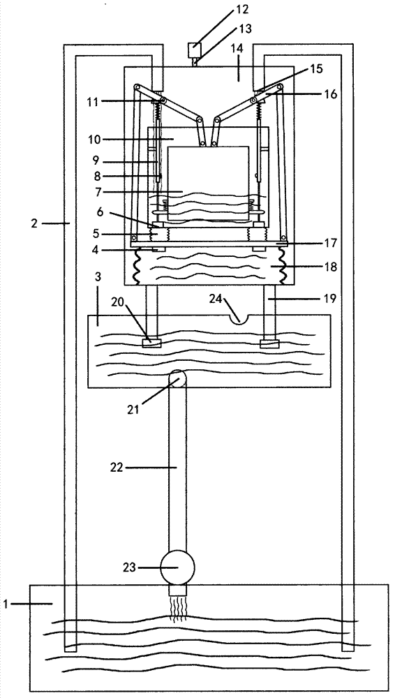
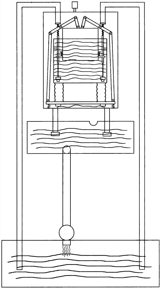
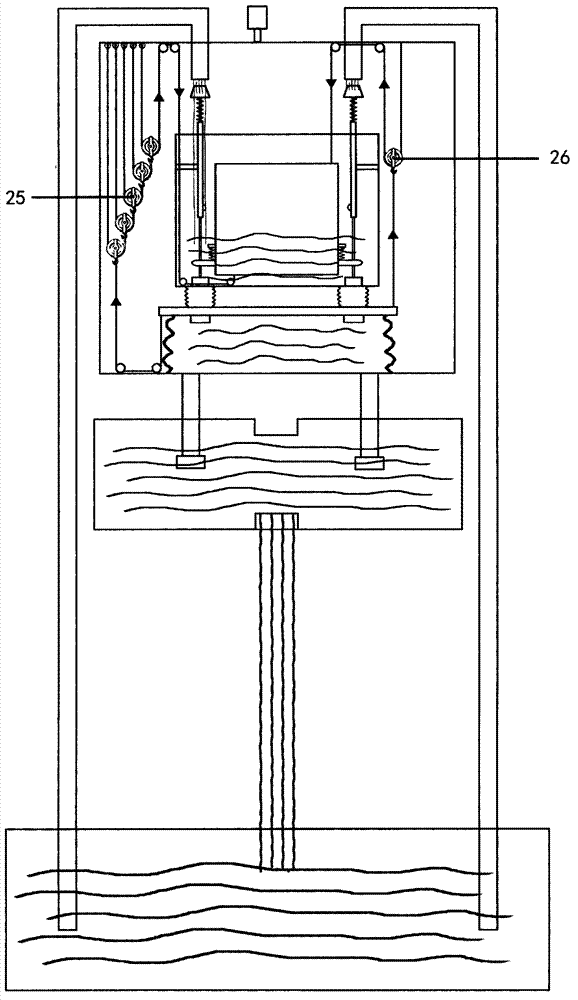
[0020] When running the environment-friendly power machine, first use the vacuum pump 12 to evacuate the vacuum box 14 from the vacuum pump port 13, then the air pressure can press the liquid in the main liquid pool 1 from the liquid inlet pipe 2 through the liquid inlet 15 into the liquid inlet of the vacuum box. In the tank 10, the continuously inflowing liquid floats into the buoyancy tank 7 in the liquid tank, and the buoyant tank floats to drive the lever 16 to press down the pressing plate 17, and the soft liquid sac 18 is squeezed by the pressure plate to squeeze the liquid in the sac through the vacuum tank drain pipe 19 The check valve 20 at the lower end is discharged into the liquid outlet pool 3, and the liquid in the liquid outlet pool falls from the liquid outlet 21 through the liquid outlet pipe 22 to drive the generator 23 to generate electricity and falls back into the main liquid pool. When the buoy floats to the set position, touch the switch 8 to make the sw...


PUM


Abstract

The invention relates to an environment-friendly power machine which aims at achieving the effect that liquid in a vacuum container can break through air pressure difference to flow out of the vacuum container under the condition that resources are not consumed. The technical main point is that the power machine enables liquid at the lower position to enter a liquid feeding tank of a vacuum box at the higher position through air pressure, the liquid enables a floating box in the liquid feeding tank to float, the floating box drives a lever to press down a piston under the liquid feeding tank, and the piston pushes liquid under the piston out of the vacuum box and enables the liquid drop to drive a generator to generate electricity and flow back to the lower position. The floating box floats in place to drive a mechanism to enable the liquid in the liquid feeding tank to drop to the below of the piston through an opening hole, the liquid in the liquid feeding tank flows out to enable the floating box to descend and drive the lever to pull the piston upwards. The floating box falls in place to close the opening hole of the liquid feeding tank to store liquid again. The power machine moves in circles to output electric energy or power continuously.

Description

Technical field: [0001] The environmental protection power machine is a device that uses gravity, buoyancy, and air pressure to drive liquid to flow from a low place to a high place and then fall back to a low place, continuously reciprocating and outputting power. Background technique: [0002] From ancient times to the present, people have designed many kinds of perpetual motion machines that have failed in the end. The scientific community also asserts that perpetual motion machines are impossible to create based on the law of energy conversion and conservation. [0003] Before we fully understand the endless motion and endless energy that exist widely in the universe, it is one-sided to use a law to completely deny the unknown field. Continuous utilization of the inexhaustible natural energy can create a perpetual motion machine that conforms to the law of energy conversion and conservation. Since there are eternal forces such as gravity, magnetism, buoyancy, and atmosp...

Claims


Application Information

Patent Timeline
Patent Type & Authority Applications(China)
IPC IPC(8): F03B17/04
CPCY02E10/20
Inventor 周智昂
Owner 周智昂
Learn More