Under-beam device reactor of low-energy electron accelerator
A technology of electron accelerators and low-energy electrons, which is applied in the field of low-energy electron accelerator beam device reactors, can solve problems such as time-consuming, blockage of outflow pipes, and reduced work efficiency of staff, so as to achieve the effect of improving work efficiency
- Summary
- Abstract
- Description
- Claims
- Application Information
AI Technical Summary
Problems solved by technology
Method used
Image
Examples
Embodiment 1
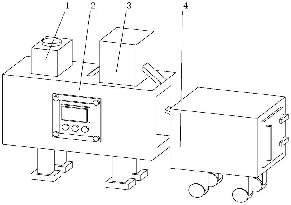
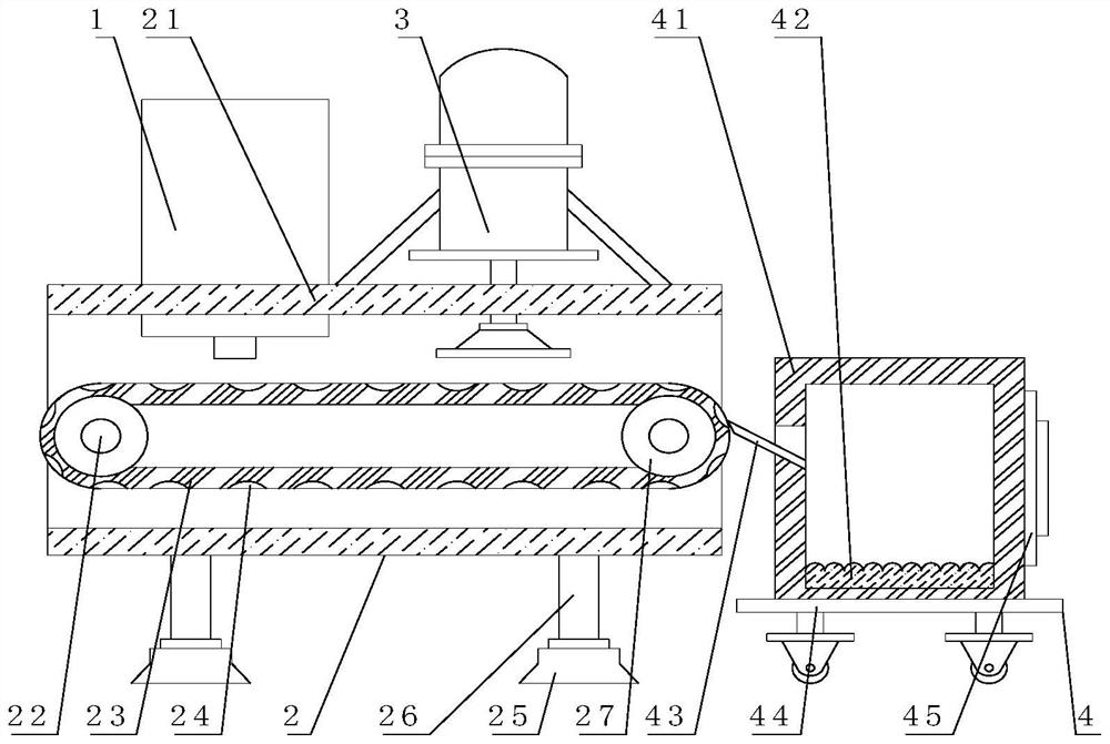
[0040] Such as Figure 1-9 As shown, the present invention provides a low-energy electron accelerator beam device reactor, comprising an electron accelerator 3 and a discharge mechanism 4, the surface of the electron accelerator 3 is provided with an auxiliary mechanism 2, and the top of the auxiliary mechanism 2 is provided with a feeding mechanism 1 , the feeding mechanism 1 includes a feeding box 11, the side of the feeding box 11 is lapped with a hammer 14, the inside of the feeding box 11 is provided with an outflow pipe 17, and the bottom of the outflow pipe 17 extends to the supply box Outside the body 11, the auxiliary mechanism 2 includes a crawler belt 23, the surface of the crawler belt 23 is provided with a limit groove 24, and the discharge mechanism 4 includes a storage box 41, the left side of the storage box 41 is provided with an inclined plate 43, and the bottom of the inner wall of the storage box 41 is fixed. A cushion pad 42 is attached.
[0041] In this ...
Embodiment 2
[0043] Such as Figure 1-9 As shown, on the basis of Embodiment 1, the present invention provides a technical solution: preferably, the side of the feed box 11 is fixedly connected with a vibrating shell 13, and the back of the inner wall of the vibrating shell 13 is fixedly connected with a No. 2 motor 16, The output end of the No. 2 motor 16 is fixedly connected with the No. 2 rotating rod 15, the front of the No. 2 rotating rod 15 is movably connected with the inner wall back of the vibration shell 13, and the surface of the No. 2 rotating rod 15 is fixedly connected with the surface of the percussion hammer 14. A fixed block 18 is fixedly connected to the right side of the outlet pipe 17 and outside the supply box 11 .
[0044] The inside of the fixed block 18 is provided with No. 3 motor 19, the output end of the No. 3 motor 19 is fixedly connected with a T-shaped plate 191, the bottom of the T-shaped plate 191 extends to the outside of the fixed block 18, and the top of ...
Embodiment 3
[0049] Such as Figure 1-9 As shown, on the basis of Embodiment 1, the present invention provides a technical solution: preferably, the inclined plate 43 includes a fixed inclined plate 431, the surface of the fixed inclined plate 431 is fixedly connected with an elastic inclined plate 432, and the surface of the fixed inclined plate 431 The inside is provided with a telescopic slot, and one side of the inner wall of the telescopic slot is fixedly connected with a telescopic rod 433, and one end of the telescopic rod 433 extends to the outside of the fixed inclined plate 431 and is fixedly connected with a slow cleaning block 434, and one side of the slow cleaning block 434 is fixed A triangular plate 435 is connected.
[0050] The surface of triangular plate 435 is fixedly connected with latex shell 436, and the inside of latex shell 436 is filled with rubber soft bag 437, and slow speed cleaning block 434 comprises triangular fixed block 4341, and the inside of triangular fi...
PUM
 Abstract
Description
Claims
Application Information
 - R&D
- Intellectual Property
- Life Sciences
- Materials
- Tech Scout
- Unparalleled Data Quality
- Higher Quality Content
- 60% Fewer Hallucinations
Browse by: Latest US Patents, China's latest patents, Technical Efficacy Thesaurus, Application Domain, Technology Topic, Popular Technical Reports.
© 2025 PatSnap. All rights reserved.Legal|Privacy policy|Modern Slavery Act Transparency Statement|Sitemap|About US| Contact US: help@patsnap.com


