Energy-saving type injection molding equipment used for double-sided injection molding and capable of preventing raw materials from overflowing

An injection molding equipment and energy-saving technology, applied in the field of energy-saving injection molding equipment, can solve the problems of incomplete product molding, insufficient injection speed, insufficient mold material, etc., and achieve the effects of reducing production volume, preventing backflow, and saving materials

Inactive Publication Date: 2021-02-02
海宁市兴华塑料制品厂
View PDF0 Cites 0 Cited by
  • Summary
  • Abstract
  • Description
  • Claims
  • Application Information

AI Technical Summary

Problems solved by technology

[0003] However, in the process of feeding the existing equipment, the residual material in the injection tube will flow out through the injection port, resulting in waste of material. In addition, the injection speed is insufficient, and the material inside the mold is not enough, which easily leads to poor molding of the product. complete, resulting in defective

Method used


Image

  • Energy-saving type injection molding equipment used for double-sided injection molding and capable of preventing raw materials from overflowing
  • Energy-saving type injection molding equipment used for double-sided injection molding and capable of preventing raw materials from overflowing
  • Energy-saving type injection molding equipment used for double-sided injection molding and capable of preventing raw materials from overflowing

Examples


Embodiment Construction

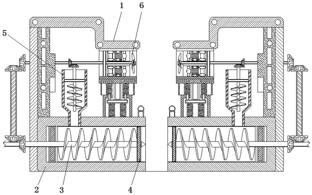
[0022] The following will clearly and completely describe the technical solutions in the embodiments of the present invention with reference to the accompanying drawings in the embodiments of the present invention. Obviously, the described embodiments are only some, not all, embodiments of the present invention. Based on the embodiments of the present invention, all other embodiments obtained by persons of ordinary skill in the art without making creative efforts belong to the protection scope of the present invention.

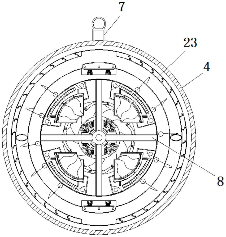
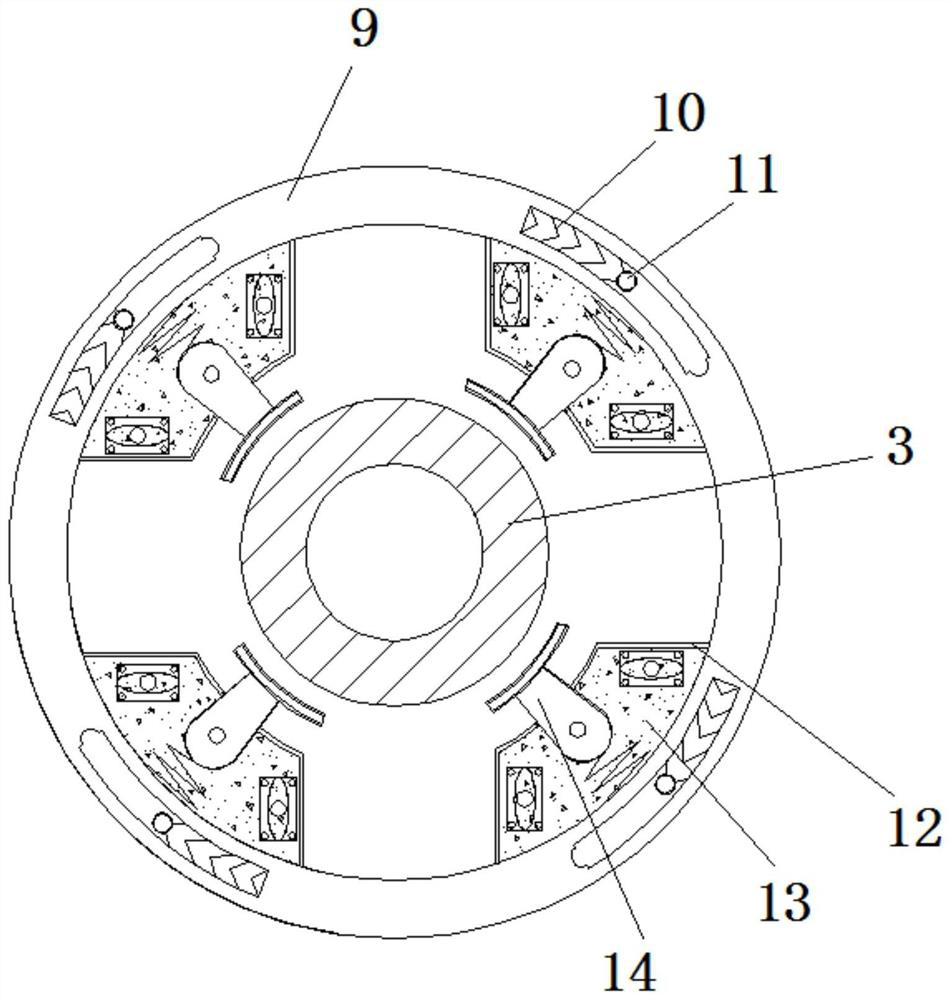
[0023] see Figure 1-6 , an energy-saving injection molding equipment used for double-sided injection molding to prevent raw materials from spilling, comprising a main body 1, an injection tube 2 is fixedly connected to the right side of the main body 1, and a screw rod 3 is inserted into the inside of the injection tube 2, and the screw rod The outside of the right end of 3 is sleeved with a fixed plate 4, the upper surface of the injection pipe 2 is plugged ...


PUM


Abstract

The invention relates to the technical field of plastic injection molding equipment, in particular to energy-saving type injection molding equipment used for double-sided injection molding and capableof preventing raw materials from overflowing. The energy-saving type injection molding equipment comprises an equipment body, an injection pipe is fixedly connected to the right side face of the equipment body, a screw rod is inserted into the injection pipe, the right end of the screw rod is connected with a fixing plate in a sleeved mode, a feeding hopper is inserted into the upper surface of the injection pipe, and a gas treatment box is fixedly connected to the position, located above the injection pipe, of the lower surface of the equipment body. A shielding plate is made to move towardsthe outer side of a limiting plate, so that an injection molding opening is blocked by the shielding plate, the problem that residual materials in the injection pipe can flow out through the injection molding opening is solved, meanwhile, materials are prevented from flowing back in the injection molding process, a conducting strip on a limiting spring cannot be connected with a second interfaceof a circuit tube through centrifugal force generated by the equipment, so that a signal lamp on the upper surface of the injection pipe is off, workers are reminded to maintain the equipment, and theproduction quantity of defective goods is reduced.

Description

technical field [0001] The invention relates to the technical field of plastic injection molding equipment, in particular to an energy-saving injection molding equipment used for double-sided injection molding to prevent overflow of raw materials. Background technique [0002] Injection molding is a method of producing shapes for industrial products. Products usually use rubber injection molding and plastic injection molding. Injection molding can also be divided into injection molding molding method and die-casting method. At present, the injection devices of general injection machines on the market adopt the method of direct feeding. [0003] However, in the process of feeding the existing equipment, the residual material in the injection tube will flow out through the injection port, resulting in waste of material. In addition, the injection speed is insufficient, and the material inside the mold is not enough, which easily leads to poor molding of the product. Complete...

Claims


Application Information

Patent Timeline
Patent Type & Authority Applications(China)
IPC IPC(8): B29C45/03B29C45/47B29C45/58
CPCB29C45/0025B29C45/03B29C45/47B29C45/581
Inventor 俞国华
Owner 海宁市兴华塑料制品厂
Why Eureka
Try Eureka