Duplex constant-speed driving shaft

A constant-velocity drive shaft and intermediate shaft technology, used in couplings, elastic couplings, engine components, etc., can solve the problems affecting the performance output and safety of the vehicle, insufficient torque output, and insufficient strength. Improve the maximum bearable torque output, high torsional strength and good lubrication effect

Active Publication Date: 2015-04-29
ZHEJIANG ODM TRANSMISSION TECH
View PDF7 Cites 0 Cited by
  • Summary
  • Abstract
  • Description
  • Claims
  • Application Information

AI Technical Summary

Problems solved by technology

The above structure can meet the needs of daily passenger cars, but when the car is running on harsh roads such as mountains and Gobi, the existing constant velocity drive shaft will show insufficient torque output, insufficient strength, and the cumulative fit clearance of multiple parts of the product. Abnormal noise and other phenomena will affect the performance output and safety of the vehicle

Method used


Image

  • Duplex constant-speed driving shaft
  • Duplex constant-speed driving shaft
  • Duplex constant-speed driving shaft

Examples


Embodiment Construction

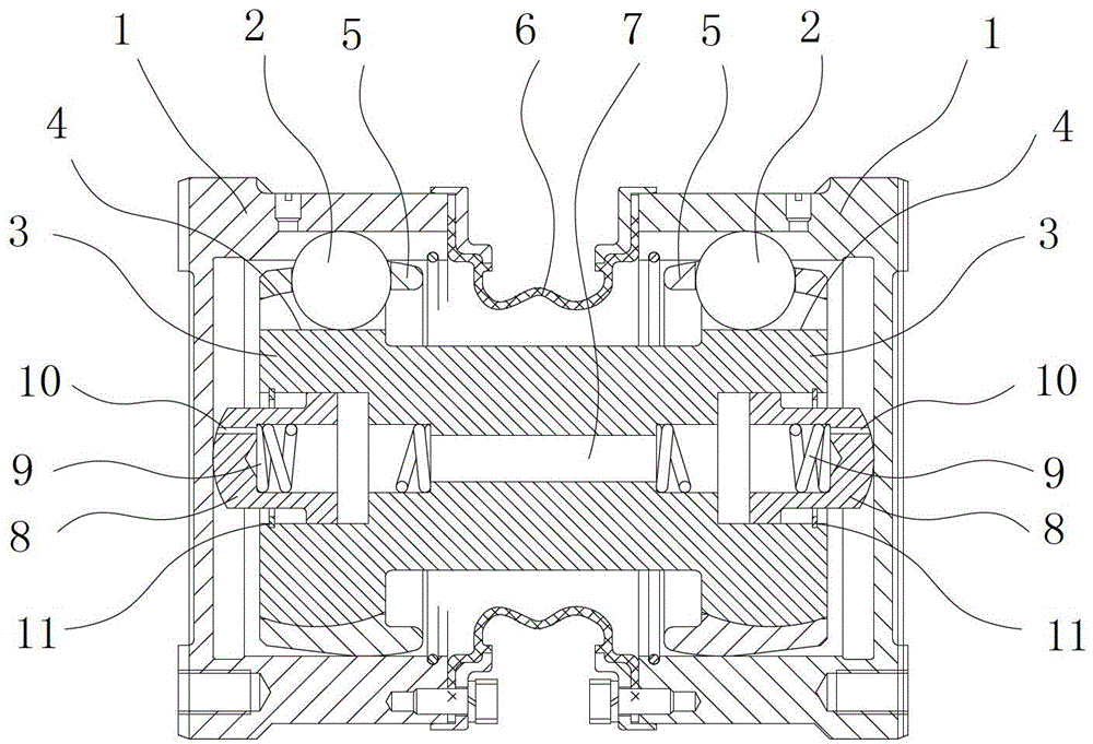
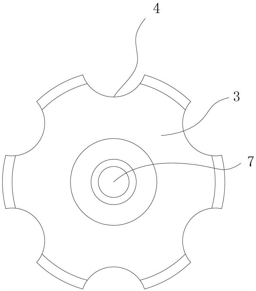
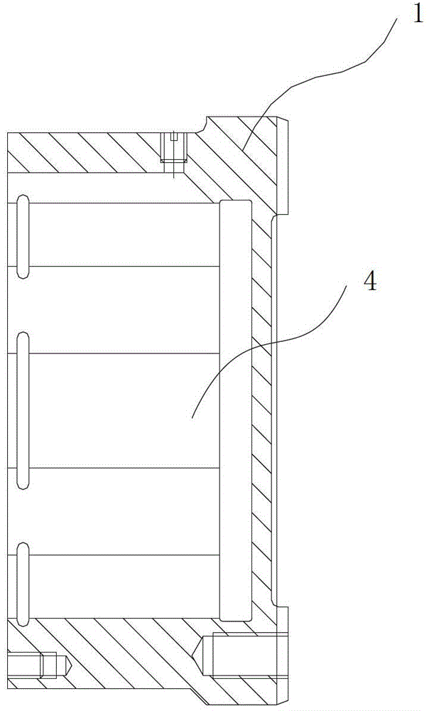
[0021] Such as Figure 1 to 5 As shown, a double-linked constant velocity drive shaft includes an intermediate shaft 3, both ends of the intermediate shaft 3 are respectively sleeved with a universal joint casing 1, and the side wall of the intermediate shaft 3 is sleeved on it Steel balls 2 are provided between the inner walls of the two universal joint casings 1 on the upper side, and steel balls 2 are provided on both side walls of the intermediate shaft 3 and the inner walls of the two universal joint casings 1. Fairway 4. A limit block 8 is provided between the end of the intermediate shaft 3 and the bottom wall of the universal joint casing 1 provided at the end, and the end of the intermediate shaft 3 is provided with a groove for accommodating the limit block 8. The groove is provided with a spring 9 which presses the limit block 8 to make the limit block 8 abut on the bottom wall of the universal joint casing 1 at the end. The inner wall of the groove is provided wit...


PUM


Abstract

The invention provides a duplex constant-speed driving shaft. The driving shaft comprises a middle shaft, wherein a cardan joint outer sleeve is sleeved at two ends of the middle shaft respectively, steel balls are arranged on the side wall of the middle shaft and arranged between inner walls of the two cardan joint outer sleeves which are sleeved on the middle shaft, and ball channels which accommodate the steel balls are arranged on side walls of two ends of the middle shaft and on inner walls of the two cardan joint outer sleeves. According to the driving shaft, the strength of the driving shaft and the maximum bearable torque output can be improved substantially, the accumulative clearance of the product is reduced, the accuracy of the product is improved, the lubricating effect is good, heat radiating is achieved fast, products are matched well, the torsional strength is high, and the product can restore in place quickly after swinging and sliding axially.

Description

Technical field [0001] The invention relates to a double-linked constant velocity drive shaft. Background technique [0002] The existing constant velocity drive shafts for automobiles generally have a structure of "fixed constant velocity universal joint + intermediate shaft + telescopic constant velocity universal joint". The fixed constant velocity universal joint consists of a bell-shaped shell, The inner star wheel, the cage and several steel balls are composed. The telescopic constant velocity universal joint is composed of sliding sleeve and three-pin joint components. The fixed constant velocity universal joint and the telescopic constant velocity universal joint are connected by an intermediate shaft, thereby Realize the function of torque transmission, swing angle and length compensation of the drive shaft. The above structure can meet the needs of daily passenger cars, but when the car is driving on harsh roads such as mountains and Gobi, the existing constant velocit...

Claims


Application Information

Patent Timeline
Patent Type & Authority Patents(China)
IPC IPC(8): F16D3/223F16D3/84F16N1/00
Inventor 王立军林永庆赵国华
Owner ZHEJIANG ODM TRANSMISSION TECH
Why Eureka
Try Eureka