

Steel grating, using device and production method
A steel grating and flat steel technology, applied in the field of steel grating manufacturing, can solve the problems of complex power consumption of equipment and large equipment investment, and achieve the effects of simple and practical process, low production cost, and saving a large amount of electric energy consumption.
- Summary
- Abstract
- Description
- Claims
- Application Information
AI Technical Summary
Problems solved by technology
Method used
Image

Examples
Embodiment 1
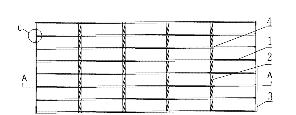
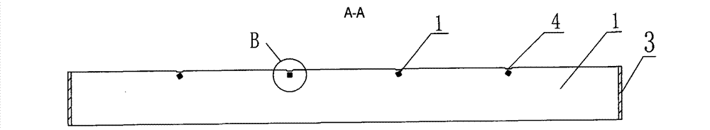
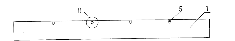
[0069] Such as Figure 1 to Figure 5 , Figure 7 to Figure 10 As shown, a steel grating of the present invention includes a flat steel 1 and a cross bar 2, and each flat steel 1 is provided with two or more through holes 5, and in this embodiment, each flat steel 1 is provided with four Through holes 5, four through holes 5 are arranged at equal intervals. The through hole 5 is adapted to the outer wall of the cross bar 2 , that is, the cross bar 2 can only pass through the through hole 5 on the flat steel 1 . Each crossbar 2 passes through the corresponding through holes 5 of all the flat steels. In this embodiment, each crossbar 2 passes through eight flat steels 1 . Corresponding to the top of each through hole 5, there is an indentation groove 4 on the top of the flat steel 1. Under the downward transmission of pressure, the indentation groove 4 corresponding to the lower cross bar also deforms and forms an extrusion pit. A left bulge 8 and a right bulge 7 are respectiv...
Embodiment 2
[0073] Example 2 as Figure 11 to Figure 13 As shown, the indentation groove 4 is provided with a clamping groove corresponding to the lower cross bar, and the clamping groove is an annular groove 6 . The outer wall of the through hole 5 is snapped into the slot. Other structures are with embodiment 1. Due to the application of pressure, the outer wall of the through hole 5 is firmly clamped in the outer wall of the annular groove 6, so that the cross bar 2 can neither move nor rotate in the through hole. This structure can make the pressing pressure smaller than that of Embodiment 1 to realize the connection.
Embodiment 3
[0075] The steel grating of embodiment 3 is as Figure 14 to Figure 17 As shown, the clamping groove is an upper concave flat groove 10, the upper concave flat groove 10 is located at the top of the cross bar 2, and the outer wall of the through hole 5 is clamped in the clamping groove. Other structures are with embodiment 2. By applying pressure, the outer wall of the through hole 5 is firmly clamped in the upper concave flat groove 10, so that the cross bar 2 can neither move nor rotate in the through hole.
PUM
 Abstract
Description
Claims
Application Information