
An electronic expansion valve

An electronic expansion valve and valve stem technology, which is applied in refrigerators, climate sustainability, lighting and heating equipment, etc., can solve problems such as easy leakage, poor sealing performance, looseness and disengagement, and achieve low leakage rate and improved sealing Performance, the effect of avoiding looseness and disengagement

Active Publication Date: 2014-10-29
ZHEJIANG SANHUA COMMERCIAL REFRIGERATION CONTROLS CO LTD SHAOXING CITY
View PDF6 Cites 0 Cited by
  • Summary
  • Abstract
  • Description
  • Claims
  • Application Information

AI Technical Summary

Problems solved by technology

[0005] First, if figure 1 As shown, the valve stem 2' is a split structure, including a conical pipe section 2'1, a sealing plate 2'3 and a cylindrical pipe section 2'2. The three are connected by threads or other connection methods. The vibration of the compressor will cause the valve rod 2' to have the risk of loosening and disengaging;
[0006] Second, if figure 1 As shown, the sealing sheet is a metal part. When the sealing sheet 2'3 closes the valve port 1'1, the sealing sheet 2'3 will contact and seal with the valve port 1'1. This kind of contact sealing is metal to metal Contact seal, easy to leak, poor sealing performance;
[0007] Third, if figure 2 As shown, since the valve stem 2' is provided with a conical pipe section 2'1 at its lower end, at the position of the valve port 1'1, the pressure of the refrigerant generally has three pressure levels, which are respectively the A pressure level with the highest pressure (horizontal The densest position of the schematic line), the B pressure level with the middle pressure (the denser position of the horizontal schematic line), and the C pressure level with the smallest pressure (the sparsest position of the horizontal schematic line), so the different positions of the conical pipe section 2′1 are respectively affected by the above-mentioned Three different pressures; such as figure 2 As shown, the opening of the lower end of the balance channel 2′4 extends into the area where the pressure grade A is located, so the pressure on the upper end of the valve stem 2′ is all pressure grade A; Under the premise of the same force area, the force on the upper end of the valve stem 2' is not equal to the force on the lower end (that is, the conical pipe section 2'1), that is, the pressure of the refrigerant on the valve stem 2' Unbalanced, which in turn affects the stability of the axial movement of the stem 2'
[0009] In view of this, how to improve the electronic expansion valve in the prior art, so that on the one hand, the danger of the valve stem being loosened and disengaged due to vibration can be avoided, and on the other hand, the sealing performance of the valve stem can be improved. Urgent problems

Method used


Image

  • An electronic expansion valve
  • An electronic expansion valve
  • An electronic expansion valve

Examples


Embodiment Construction

[0043] The core of the present invention is to provide an electronic expansion valve. The structural design of the electronic expansion valve can avoid the risk of the valve stem being loosened and disengaged due to vibration on the one hand, and can improve the sealing performance of the valve stem on the other hand.

[0044] In order to enable those skilled in the art to better understand the technical solutions of the present invention, the present invention will be further described in detail below in conjunction with the accompanying drawings and specific embodiments.

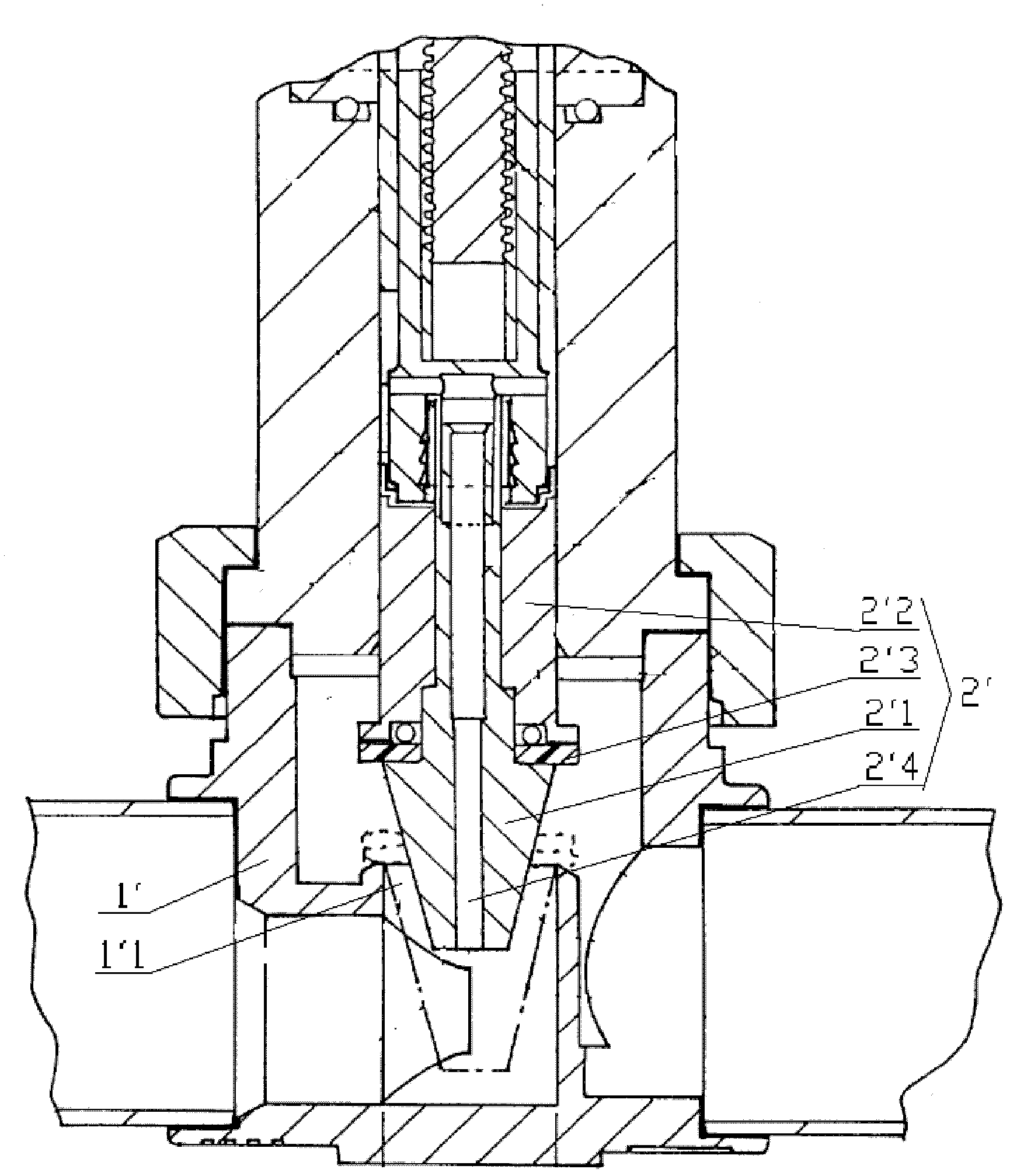
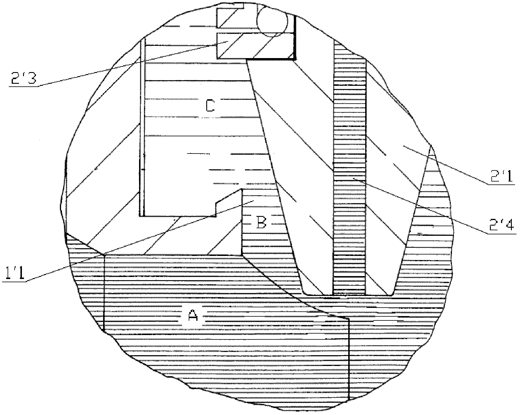
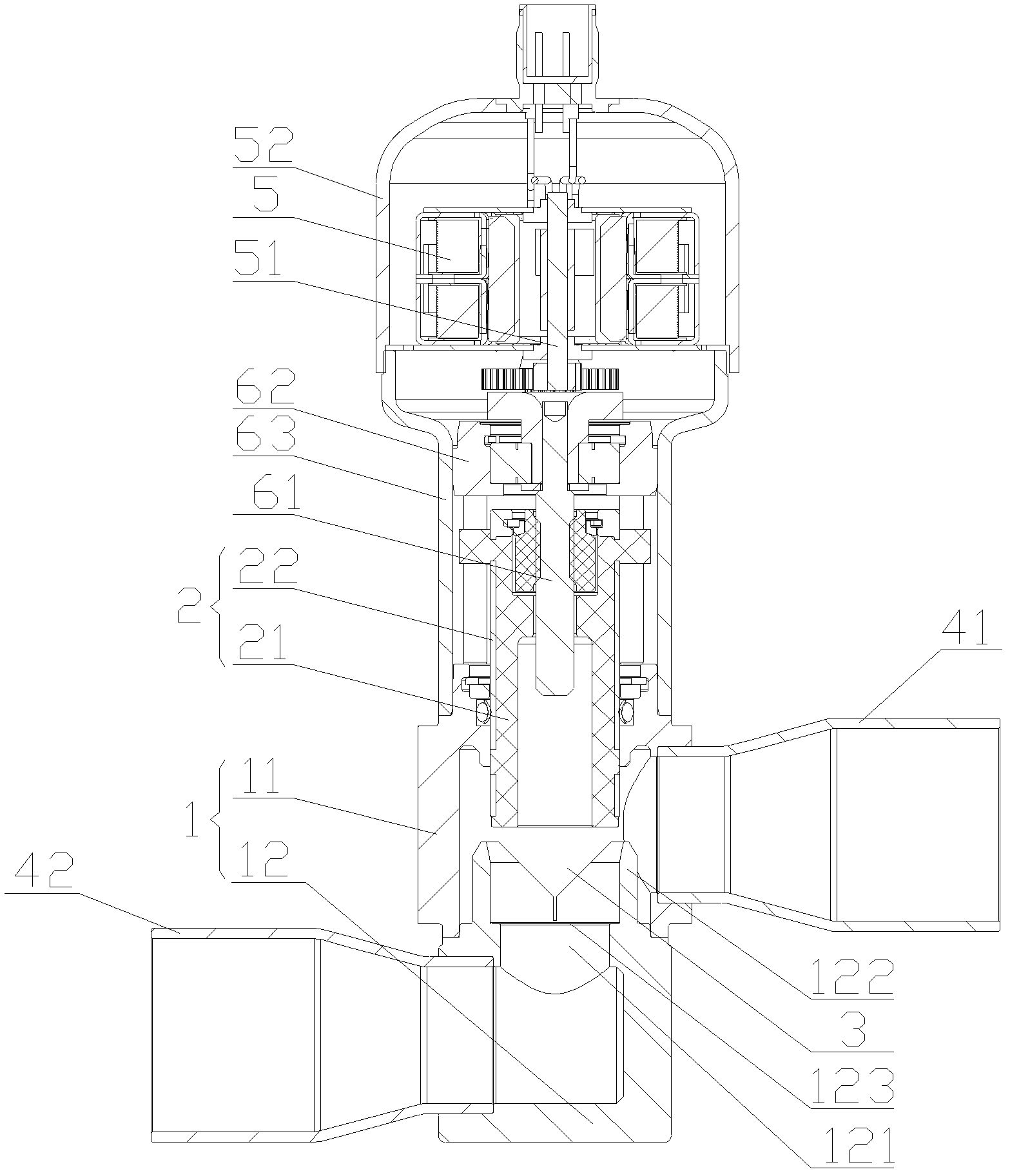
[0045] Please refer to image 3 , Figure 4 , Pic 4-1 , Figure 4-2 and Figure 4-3 , image 3 It is a schematic structural diagram of an electronic expansion valve in an embodiment of the present invention; Figure 4 for image 3Schematic diagram of the structure of the valve stem of the electronic expansion valve; Pic 4-1 for Figure 4 Sectional view of the valve stem; Figure 4-2 for Pic 4-...


PUM


Abstract

The invention discloses an electronic expansion valve. The electronic expansion valve comprises a valve seat (1) and a valve rod (2), wherein the valve seat (1) is provided with a valve port (121) inside the cavity of the valve seat; the electronic expansion valve also comprises a motor shell and a motor arranged in the motor shell, wherein the motor drives the valve rod to axially move to regulate the refrigerant flow passing through the valve port; the valve rod (2) comprises a matrix (21) integrally formed by injection-molding non-metallic materials; and the matrix (21) is in contact seal or not in contact with the corresponding position of the valve port (121). The electronic expansion valve has the following beneficial effects that through the structural design, on one hand, the danger that the valve rod (2) is loosened and disconnected due to vibration can be avoided, and on the other hand, the sealing property of the valve rod (2) can be improved.

Description

technical field [0001] The invention relates to the technical field of fluid control components, in particular to an electronic expansion valve. Background technique [0002] The electronic expansion valve is an important part of the refrigeration system, and it is another basic part of the four basic components of the refrigeration system except the evaporator, compressor and condenser. The working process of the electronic expansion valve is generally: as the coil device is energized or de-energized, the valve needle adjusts the opening of the valve port, thereby adjusting the flow rate of the refrigerant. [0003] In the prior art, the US patent No. US6568656B1 discloses an electronic expansion valve, please refer to figure 1 and figure 2 , figure 1 It is a structural schematic diagram of an electronic expansion valve in the prior art, figure 2 for figure 1 Schematic diagram of the pressure distribution of the refrigerant at the valve port position of the electroni...

Claims


Application Information

Patent Timeline
Patent Type & Authority Patents(China)
IPC IPC(8): F25B41/06
CPCY02B30/72Y02B30/70
Inventor 不公告发明人
Owner ZHEJIANG SANHUA COMMERCIAL REFRIGERATION CONTROLS CO LTD SHAOXING CITY
Features
  • Generate Ideas
  • Intellectual Property
  • Life Sciences
  • Materials
  • Tech Scout
  • Unparalleled Data Quality
  • Higher Quality Content
  • 60% Fewer Hallucinations
Learn More